Dell Alienware m18 R2 Owners Manual - Page 54
Steps, Next steps
 |
View all Dell Alienware m18 R2 manuals
Add to My Manuals
Save this manual to your list of manuals |
Page 54 highlights
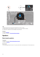
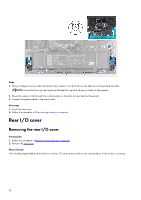
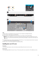
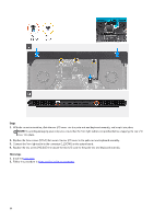
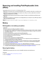
Steps 1. With the correct orientation, slide the rear I/O cover into the palm-rest and keyboard assembly, and snap it into place. NOTE: To avoiding damaging your computer, ensure that the Tron-light cable is not pinched before snapping the rear I/O cover into place. 2. Replace the three screws (M2x3) that secure the rear I/O cover to the palm-rest and keyboard assembly. 3. Connect the Tron-light cable to the connector (LEDON1) on the system board. 4. Replace the two screws (M2.5x5) that secure the rear I/O cover to the palm-rest and keyboard assembly. Next steps 1. Install the base cover. 2. Follow the procedure in After working inside your computer. 54
-
 1
1 -
2
-
3
-
4
-
5
-
6
-
7
-
8
-
9
-
10
-
11
-
12
-
13
-
14
-
15
-
16
-
17
-
18
-
19
-
20
-
21
-
22
-
23
-
24
-
25
-
26
-
27
-
28
-
29
-
30
-
31
-
32
-
33
-
34
-
35
-
36
-
37
-
38
-
39
-
40
-
41
-
42
-
43
-
44
-
45
-
46
-
47
-
48
-
 49
49 -
 50
50 -
 51
51 -
 52
52 -
 53
53 -
 54
54 -
 55
55 -
 56
56 -
 57
57 -
 58
58 -
 59
59 -
60
-
61
-
62
-
63
-
64
-
65
-
66
-
67
-
68
-
69
-
70
-
71
-
72
-
73
-
74
-
75
-
76
-
77
-
78
-
79
-
80
-
81
-
82
-
83
-
84
-
85
-
86
-
87
-
88
-
89
-
90
-
91
-
92
-
93
-
94
-
95
-
96
-
97
-
98
-
99
-
100
-
101
-
102
-
103
-
104
-
105
-
106
-
107
-
108
-
109
-
110
-
111
-
112
-
113
-
114
-
115
-
116
-
117
-
118
-
119
-
120
-
121
-
122
-
123
-
124
-
125
 |
 |

Steps
1.
With the correct orientation, slide the rear I/O cover into the palm-rest and keyboard assembly, and snap it into place.
NOTE:
To avoiding damaging your computer, ensure that the Tron-light cable is not pinched before snapping the rear I/O
cover into place.
2.
Replace the three screws (M2x3) that secure the rear I/O cover to the palm-rest and keyboard assembly.
3.
Connect the Tron-light cable to the connector (LEDON1) on the system board.
4.
Replace the two screws (M2.5x5) that secure the rear I/O cover to the palm-rest and keyboard assembly.
Next steps
1.
Install the
base cover
.
2.
Follow the procedure in
After working inside your computer
.
54