Dell Alienware m18 R2 Owners Manual - Page 96
Palm-rest and keyboard assembly
 |
View all Dell Alienware m18 R2 manuals
Add to My Manuals
Save this manual to your list of manuals |
Page 96 highlights
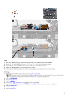
Palm-rest and keyboard assembly Removing the palm-rest and keyboard assembly CAUTION: The information in this removal section is intended for authorized service technicians only. Prerequisites 1. Follow the procedure in Before working inside your computer. 2. Remove the base cover. 3. Remove the battery. 4. Remove the wireless card. 5. Remove the memory module. 6. Remove the M.2 2280 solid state drive or M.2 2230 solid-state drive in slot one and two, whichever is applicable. 7. Remove the M.2 2230 solid-state drive in slot three and four, if applicable. 8. Remove the small fan. 9. Remove the top heat-sink. 10. Remove the rear I/O cover. 11. Remove the touchpad. 12. Remove the keyboard-controller board. 13. Remove the USB Type-C board. 14. Remove the speakers. 15. Remove the power-adapter port. 16. Remove the display assembly. 17. Follow the procedure from step 1 to step 20 in Removing the system board. NOTE: The system board can be removed and installed along with the audio board and heat-sink assembly. This simplifies the removal and installation procedure and avoids breaking the thermal bond between the system board and heat sink. 18. Remove the antennas 19. Remove the power button. 20.Remove the I/O board. About this task The following images indicate the location of the palm-rest and keyboard assembly and provide a visual representation of the removal procedure. 96
-
 1
1 -
2
-
3
-
4
-
5
-
6
-
7
-
8
-
9
-
10
-
11
-
12
-
13
-
14
-
15
-
16
-
17
-
18
-
19
-
20
-
21
-
22
-
23
-
24
-
25
-
26
-
27
-
28
-
29
-
30
-
31
-
32
-
33
-
34
-
35
-
36
-
37
-
38
-
39
-
40
-
41
-
42
-
43
-
44
-
45
-
46
-
47
-
48
-
49
-
50
-
51
-
52
-
53
-
54
-
55
-
56
-
57
-
58
-
59
-
60
-
61
-
62
-
63
-
64
-
65
-
66
-
67
-
68
-
69
-
70
-
71
-
72
-
73
-
74
-
75
-
76
-
77
-
78
-
79
-
80
-
81
-
82
-
83
-
84
-
85
-
86
-
87
-
88
-
89
-
90
-
 91
91 -
 92
92 -
 93
93 -
 94
94 -
 95
95 -
 96
96 -
 97
97 -
 98
98 -
 99
99 -
 100
100 -
 101
101 -
102
-
103
-
104
-
105
-
106
-
107
-
108
-
109
-
110
-
111
-
112
-
113
-
114
-
115
-
116
-
117
-
118
-
119
-
120
-
121
-
122
-
123
-
124
-
125
 |
 |
