Dell Inspiron 14 Owner's Manual - Page 66
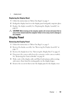
Replacing the Display Panel
 |
View all Dell Inspiron 14 manuals
Add to My Manuals
Save this manual to your list of manuals |
Page 66 highlights
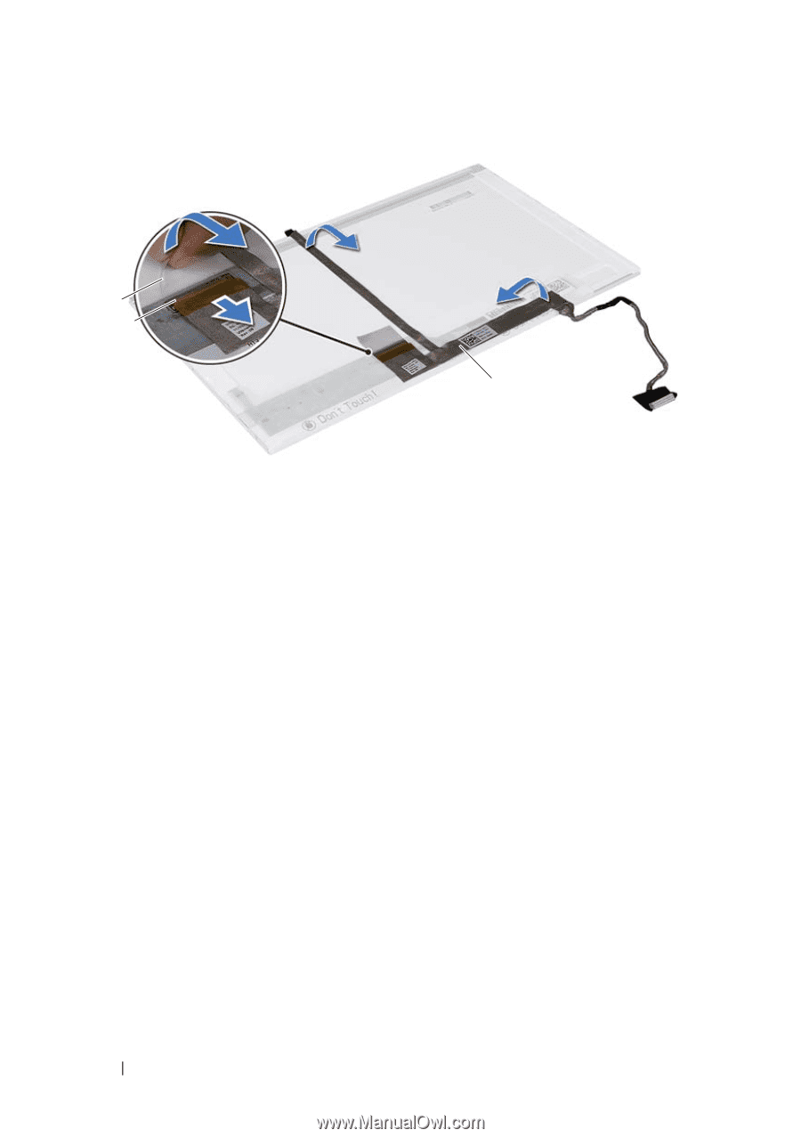
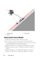
1 2 3 1 tape 3 display cable 2 display-board connector Replacing the Display Panel 1 Follow the instructions in "Before You Begin" on page 9. 2 Attach the display cable to the back of the display panel. 3 Connect the display cable to the display-board connector and secure it with the tape. 4 Turn the display panel over. 5 Align the screw holes on the display-panel bracket with the screw holes on the display panel and replace the four screws (two on each side). 6 Align the screw holes on the display panel with the screw holes on the display cover and replace the six screws. 7 Route the display cable and Mini-Card antenna cables through the routing guides on the display hinges. 8 Connect the camera cable to the connector on the camera module. See "Replacing the Camera Module" on page 70. 9 Replace the display bezel. See "Replacing the Display Bezel" on page 63. 10 Replace the display assembly. See "Replacing the Display Assembly" on page 61. 66 Display
-
 1
1 -
2
-
3
-
4
-
5
-
6
-
7
-
8
-
9
-
10
-
11
-
12
-
13
-
14
-
15
-
16
-
17
-
18
-
19
-
20
-
21
-
22
-
23
-
24
-
25
-
26
-
27
-
28
-
29
-
30
-
31
-
32
-
33
-
34
-
35
-
36
-
37
-
38
-
39
-
40
-
41
-
42
-
43
-
44
-
45
-
46
-
47
-
48
-
49
-
50
-
51
-
52
-
53
-
54
-
55
-
56
-
57
-
58
-
59
-
60
-
 61
61 -
 62
62 -
 63
63 -
 64
64 -
 65
65 -
 66
66 -
 67
67 -
 68
68 -
 69
69 -
 70
70 -
 71
71 -
72
-
73
-
74
-
75
-
76
-
77
-
78
 |
 |