Dell Inspiron 17 N7010 Inspiron 17 N7010 Service Manual - Page 60
display cable
 |
View all Dell Inspiron 17 N7010 manuals
Add to My Manuals
Save this manual to your list of manuals |
Page 60 highlights
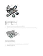
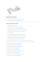
1 display cable grounding screw 3 AC adapter connector cable 5 speaker cable 2 display cable 4 subwoofer cable 6 status light board cable 16. Remove the eight screws that secure the system board assembly to the computer base. 17. Carefully ease the connectors on the system board assembly out of the slots in the computer, and lift the system board assembly off the computer base. 1 system board assembly 2 screws (8) 18. Turn the system board assembly over. 19. Loosen the two captive screws that secure the platform controller hub (PCH) cooler to the system board. 20. Lift the PCH cooler off the system board.
-
 1
1 -
2
-
3
-
4
-
5
-
6
-
7
-
8
-
9
-
10
-
11
-
12
-
13
-
14
-
15
-
16
-
17
-
18
-
19
-
20
-
21
-
22
-
23
-
24
-
25
-
26
-
27
-
28
-
29
-
30
-
31
-
32
-
33
-
34
-
35
-
36
-
37
-
38
-
39
-
40
-
41
-
42
-
43
-
44
-
45
-
46
-
47
-
48
-
49
-
50
-
51
-
52
-
53
-
54
-
 55
55 -
 56
56 -
 57
57 -
 58
58 -
 59
59 -
 60
60 -
 61
61 -
 62
62 -
 63
63
 |
 |

16.
Remove the eight screws that secure the system board assembly to the computer base.
17.
Carefully ease the connectors on the system board assembly out of the slots in the computer, and lift the system board assembly off the computer
base.
18.
Turn the system board assembly over.
19.
Loosen the two captive screws that secure the platform controller hub (PCH) cooler to the system board.
20.
Lift the PCH cooler off the system board.
1
display cable grounding
screw
2
display cable
3
AC adapter connector
cable
4
subwoofer cable
5
speaker cable
6
status light board
cable
1
system board assembly
2
screws (8)