Dell Inspiron 24 5420 All-in-One Owners Manual
Dell Inspiron 24 5420 All-in-One Manual
 |
View all Dell Inspiron 24 5420 All-in-One manuals
Add to My Manuals
Save this manual to your list of manuals |
Dell Inspiron 24 5420 All-in-One manual content summary:
- Dell Inspiron 24 5420 All-in-One | Owners Manual - Page 1
Inspiron 24 5420 All-in-One Owner's Manual Regulatory Model: W29C Regulatory Type: W29C001 March 2023 Rev. A00 - Dell Inspiron 24 5420 All-in-One | Owners Manual - Page 2
use of your product. CAUTION: A CAUTION indicates either potential damage to hardware or loss of data and tells you how to avoid the problem. WARNING: A WARNING indicates a potential for property damage, personal injury, or death. © 2023 Dell Inc. or its subsidiaries. All rights reserved. Dell - Dell Inspiron 24 5420 All-in-One | Owners Manual - Page 3
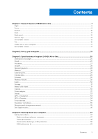
All-in-One 7 Right...8 Front...9 Bottom...10 Back...11 Back panel...12 Service Tag...13 Retractable camera ...13 Tilt...15 Inside view of your computer...17 Retractable environment...35 Dell Support policy...36 Chapter 4: Working inside your computer 37 Safety instructions...37 Before working - Dell Inspiron 24 5420 All-in-One | Owners Manual - Page 4
Transporting sensitive components...40 After working inside your computer...40 BitLocker...40 Recommended tools...40 Screw list...41 Major components of Inspiron 24 5420 All-in-One 42 Chapter 5: Removing and installing Customer Replaceable Units (CRUs 45 Stand...45 Removing the stand...45 - Dell Inspiron 24 5420 All-in-One | Owners Manual - Page 5
Chapter 6: Removing and installing Field Replaceable Units (FRUs 74 Heat sink (integrated graphics)...74 Removing the heat sink...74 Installing the heat sink...75 Heat sink (discrete graphics)...76 Removing the heat sink...76 Installing the heat sink...77 Media-card reader...78 Removing the media- - Dell Inspiron 24 5420 All-in-One | Owners Manual - Page 6
Chapter 9: Troubleshooting...115 Dell SupportAssist Pre-boot System Performance Check diagnostics 115 Running the SupportAssist Pre-Boot System Performance Check 115 System-diagnostic lights...115 Recovering the - Dell Inspiron 24 5420 All-in-One | Owners Manual - Page 7
1 Views of Inspiron 24 5420 All-in-One 7 - Dell Inspiron 24 5420 All-in-One | Owners Manual - Page 8
Right Views of Inspiron 24 5420 All-in-One 8 Views of Inspiron 24 5420 All-in-One - Dell Inspiron 24 5420 All-in-One | Owners Manual - Page 9
1. USB 3.2 Gen 2 Type-C port Connect devices such as external storage devices and printers. Provides data transfer speeds up to 10 Gbps. PowerShare enables you to charge connected USB devices. NOTE: Connected USB devices will not charge when the computer is turned off or in sleep state. Turn on the - Dell Inspiron 24 5420 All-in-One | Owners Manual - Page 10
appear on the screen. For more information, see the Troubleshooting section in the Service Manual at www.dell.com/support/manuals. 3. Service Tag label The Service Tag is a unique alphanumeric identifier that enables Dell service technicians to identify the hardware components in your computer and - Dell Inspiron 24 5420 All-in-One | Owners Manual - Page 11
Back 1. Back cover Removable chassis. 2. Back panel Connect USB, audio, video, and other devices. 3. Stand Allows the system to be mounted vertically. For more information on the rear ports, see Back panel. Views of Inspiron 24 5420 All-in-One 11 - Dell Inspiron 24 5420 All-in-One | Owners Manual - Page 12
BIOS Deep Sleep control to disabled to start charging when the computer is powered off. 7. USB 3.2 Gen 1 port with Power on/Wake-up support Connect peripherals such as external storage devices and printers. Provides data transfer speeds up to 5 Gbps. Wake the computer from standby with the keyboard - Dell Inspiron 24 5420 All-in-One | Owners Manual - Page 13
, and so on. 9. SD-card slot Reads from and writes to the SD card. The computer supports the following card types: ● Secure Digital (SD) ● Secure Digital High Capacity (SDHC) ● Secure Digital Extended Capacity (SDXC) Service Tag The service tag is a unique alphanumeric identifier that allows Dell - Dell Inspiron 24 5420 All-in-One | Owners Manual - Page 14
1. Infrared emitter Emits infrared light, which enables the infrared camera to sense and track motion. 2. Infrared camera Enhances security when paired with Windows Hello face authentication. 3. Camera Enables you to video chat, capture photos, and record videos. 4. Infrared emitter Emits infrared - Dell Inspiron 24 5420 All-in-One | Owners Manual - Page 15
Tilt Y stand Views of Inspiron 24 5420 All-in-One 15 - Dell Inspiron 24 5420 All-in-One | Owners Manual - Page 16
Isosceles stand 16 Views of Inspiron 24 5420 All-in-One - Dell Inspiron 24 5420 All-in-One | Owners Manual - Page 17
Inside view of your computer 1. Heat sink 2. Fan 3. Speakers 4. Media-card reader 5. System board 6. Microphone module 7. Wireless-card slot 8. Power-button board 9. Hard-disk drive 10. Display panel 11. Display-assembly base 12. Solid-state drive slot 13. Camera module 14. Coin-cell battery 15. - Dell Inspiron 24 5420 All-in-One | Owners Manual - Page 18
18 Views of Inspiron 24 5420 All-in-One - Dell Inspiron 24 5420 All-in-One | Owners Manual - Page 19
slot on the back cover until it snaps into place. 2. Connect the keyboard and mouse. NOTE: To connect your wireless keyboard and mouse, find User Guides and other resources for your products at https://www.dell.com/support Set up your computer 19 - Dell Inspiron 24 5420 All-in-One | Owners Manual - Page 20
3. Connect to your network using a cable. 20 Set up your computer - Dell Inspiron 24 5420 All-in-One | Owners Manual - Page 21
NOTE: Alternatively, you can connect to a wireless network. 4. Connect the power cable. Set up your computer 21 - Dell Inspiron 24 5420 All-in-One | Owners Manual - Page 22
5. Press the power button. 22 Set up your computer - Dell Inspiron 24 5420 All-in-One | Owners Manual - Page 23
6. Finish Windows setup. Follow the on-screen instructions to complete the setup. When setting up, Dell recommends that account. If not connected to the internet, create an offline account. ● On the Support and Protection screen, enter your contact details. 7. Locate and use Dell apps from the - Dell Inspiron 24 5420 All-in-One | Owners Manual - Page 24
failures. For more information, see SupportAssist for Home PCs User's Guide at www.dell.com/ serviceabilitytools. Click SupportAssist and then, Update, search in the Knowledge Base Resource at www.dell.com/ support. Dell Digital Delivery Download software applications, which are purchased but not - Dell Inspiron 24 5420 All-in-One | Owners Manual - Page 25
depending on the configuration ordered and the manufacturing variability. Stand The following table provides the height, width, depth, and weight of the stand supported by yourInspiron 24 5420 All-in-One Table 3. Stand Description Y stand Isosceles stand Height 96.62 mm (3.81 in.) 97.56 mm - Dell Inspiron 24 5420 All-in-One | Owners Manual - Page 26
Y stand The following table provides the dimensions of the computer with Y stand installed. Table 4. Y stand dimensions Description Dimensions 414.30 mm (16.31 in.) 199.55 mm (7.86 in.) 390.71 mm (15.38 in.) 228.19 mm (8.98 in.) 440.30 mm (17.34 in.) 539.11 mm (21.22 in.) Isosceles stand - Dell Inspiron 24 5420 All-in-One | Owners Manual - Page 27
mm (9.01 in.) 440.30 mm (17.34 in.) 531.50 mm (20.92 in.) Processor The following table lists the details of the processors supported by your Inspiron 24 5420 All-in-One. Table 6. Processor Description Processor type Option one Option two 13th Generation Intel Core 13th Generation Intel i7 - Dell Inspiron 24 5420 All-in-One | Owners Manual - Page 28
Intel U300 DRAM bus width 128-bit Flash EPROM 32 MB PCIe bus Up to Gen4 Operating system Your Inspiron 24 5420 All-in-One supports the following operating systems: ● Windows 11 Pro ● Windows 11 Home Memory The following table lists the memory specifications of your Inspiron 24 5420 All-in - Dell Inspiron 24 5420 All-in-One | Owners Manual - Page 29
HDCP 1.4 port Media-card reader One SD-card 3.0 slot Power-adapter port One 4.50 mm x 2.90 mm DC-in port Security-cable slot Not supported Internal slots The following table lists the internal slots of your Inspiron 24 5420 All-in-One. Table 10. Internal slots Description M.2 Values ● One - Dell Inspiron 24 5420 All-in-One | Owners Manual - Page 30
specifications Description Option one Model number Intel AX201 Option two Intel AX211 Transfer rate Up to 2400 Mbps Up to 2400 Mbps Frequency bands supported 2.40 GHz/5 GHz 2.40 GHz/5 GHz/6 GHz Wireless standards ● WiFi 802.11a/b/g ● Wi-Fi 4 (WiFi 802.11n) ● Wi-Fi 5 (WiFi 802.11ac) ● Wi - Dell Inspiron 24 5420 All-in-One | Owners Manual - Page 31
M.2 2230, solid-state drive PCIe NVMe Gen4 x4, up to 64 Gbps Up to 1 TB Media-card reader The following table lists the media cards supported by your Inspiron 24 5420 All-in-One. Table 16. Media-card reader specifications Description Media-card type Values One SD-card 3.0 slot Media-cards - Dell Inspiron 24 5420 All-in-One | Owners Manual - Page 32
07 megapixel Video 1920 x 1080 (FHD) at 30 fps Infrared camera resolution: Still image Not supported Video Not supported Diagonal viewing angle: Camera 82 degrees Infrared camera Not supported Option two One FHD RGB + Infrared camera Front camera CMOS sensor technology 2.07 megapixel 1920 - Dell Inspiron 24 5420 All-in-One | Owners Manual - Page 33
type Option one 23.8-inch, Full High Definition (FHD) Option two 23.8-inch, Full High definition (FHD) Touch options Touch support with 10 touch points Not supported Display-panel technology Wide View Angle (WVA) Wide view Angle (WVA) Display-panel dimensions (active area): Height 296.46 - Dell Inspiron 24 5420 All-in-One | Owners Manual - Page 34
mm x 0.2745 mm 14.11 W Anti-glare GPU-Integrated The following table lists the specifications of the integrated Graphics Processing Unit (GPU) supported by your Inspiron 24 5420 All-in-One. Table 20. GPU-Integrated Controller Memory size Processor Intel UHD Graphics (For computers shipped with - Dell Inspiron 24 5420 All-in-One | Owners Manual - Page 35
NOTE: Wood‐based fiber packaging contains a minimum of 35% recycled content by total weight of wood‐based fiber. Packaging that contains without wood‐based fiber can be claimed as Not Applicable. The anticipated required criteria for EPEAT 2018. Regulatory compliance The following table lists the - Dell Inspiron 24 5420 All-in-One | Owners Manual - Page 36
Dell Support policy For information on Dell support policy, search in the Knowledge Base Resource at www.dell.com/support. 36 Specifications of Inspiron 24 5420 All-in-One - Dell Inspiron 24 5420 All-in-One | Owners Manual - Page 37
and the contacts. CAUTION: You should only perform troubleshooting and repairs as authorized or directed by the Dell technical assistance team. Damage due to servicing that is not authorized by Dell is not covered by your warranty. See the safety instructions that is shipped with the product or at - Dell Inspiron 24 5420 All-in-One | Owners Manual - Page 38
taken before performing any disassembly instructions. Observe the following safety potential. This is done through the use of a field service electrostatic discharge (ESD) kit. When connecting a bonding wire may not be obvious, such as intermittent problems or a shortened product life span. As the - Dell Inspiron 24 5420 All-in-One | Owners Manual - Page 39
The more difficult type of damage to recognize and troubleshoot is the intermittent (also called latent or "walking between your skin, the ESD mat, and the hardware is known as bonding. Use only Field Service kits with a wrist strap, mat, and bonding wire. Never use wireless wrist straps. Always be - Dell Inspiron 24 5420 All-in-One | Owners Manual - Page 40
parts separate from all insulator parts while performing service and that they use anti-static bags for transporting for a stable base, and point your toes out. 2. Tighten stomach muscles. Abdominal muscles support your spine when you lift, offsetting the force of the load. 3. Lift with your legs - Dell Inspiron 24 5420 All-in-One | Owners Manual - Page 41
● Phillips screwdriver #0 ● Phillips screwdriver #1 ● Plastic scribe Screw list NOTE: When removing screws from a component, it is recommended to note the screw type, the quantity of screws, and then place them in a screw storage box. This is to ensure that the correct number of screws and correct - Dell Inspiron 24 5420 All-in-One | Owners Manual - Page 42
Table 25. Screw list (continued) Component Screw type Display panel M3x5 Display panel M3x3 Quantity 10 5 Screw image Major components of Inspiron 24 5420 All-in-One The following image shows the major components of Inspiron 24 5420 All-in-One. 42 Working inside your computer - Dell Inspiron 24 5420 All-in-One | Owners Manual - Page 43
1. Back cover 3. Antennas 5. Microphone module 7. System board 2. Isosceles stand 4. Heat sink 6. Fan 8. Speaker Working inside your computer 43 - Dell Inspiron 24 5420 All-in-One | Owners Manual - Page 44
9. Middle frame 11. Power-button board with USB and connector cable 13. Media-card reader 15. Hard-disk drive 17. M.2 2230 solid-state drive 19. System-board shield 21. I/O cover 10. Base panel 12. Stand hinge 14. Display panel 16. Wireless card 18. M.2 2280 solid-state drive 20. Camera module 44 - Dell Inspiron 24 5420 All-in-One | Owners Manual - Page 45
with the stand hanging over the edge. It is recommended to remove the stand to avoid accidental damage to the computer display when servicing. NOTE: The following procedure is applicable for both Y stand and Isosceles stand. NOTE: For replacement of stand or stand hinges, the replacement kit - Dell Inspiron 24 5420 All-in-One | Owners Manual - Page 46
Steps 1. Locate the tab on the stand, and push a scribe into the tab to release the stand from the display-assembly base. 2. Lift the stand off the display-assembly base. Installing the stand Prerequisites If you are replacing a component, remove the existing component before performing the - Dell Inspiron 24 5420 All-in-One | Owners Manual - Page 47
with the stand hanging over the edge. It is recommended to remove the stand to avoid accidental damage to the computer display when servicing. About this task The following image indicates the location of the back cover and provides a visual representation of the removal procedure. Removing and - Dell Inspiron 24 5420 All-in-One | Owners Manual - Page 48
Steps 1. Place your palm in the middle of the back cover, and then pry the back cover from the display-assembly base starting from the top corners. 2. Remove the back cover from the display-assembly base. Installing the back cover Prerequisites If you are replacing a component, remove the existing - Dell Inspiron 24 5420 All-in-One | Owners Manual - Page 49
Steps Align the slots on the back cover with the slots on the computer, and press along the side to snap the back cover into place. Next steps 1. Follow the procedure in After working inside your computer. I/O cover Removing the I/O cover Prerequisites 1. Follow the procedure in Before working - Dell Inspiron 24 5420 All-in-One | Owners Manual - Page 50
Steps 1. Remove the five screws (M3x5) that secure the I/O cover to the display-assembly base. 2. Lift the I/O cover off the display-assembly base. Installing the I/O cover Prerequisites If you are replacing a component, remove the existing component before performing the installation procedure. - Dell Inspiron 24 5420 All-in-One | Owners Manual - Page 51
Steps 1. Place the I/O cover on the display-assembly base. 2. Align the screw holes on the I/O cover with the screw holes on the display-assembly base. 3. Replace the two screws (M3x5) that secure the I/O cover to the display-assembly base and snap the I/O cover back into place. Next steps 1. - Dell Inspiron 24 5420 All-in-One | Owners Manual - Page 52
Steps 1. Remove the 10 screws (M3x4.5) that secure the right and left stand hinges to the display-assembly base. 2. Lift the stand hinges off the display-assembly base. Installing the stand hinges Prerequisites If you are replacing a component, remove the existing component before performing the - Dell Inspiron 24 5420 All-in-One | Owners Manual - Page 53
Steps 1. Align the screw holes on the stand hinges with the screw holes on the display-assembly base. 2. Replace the 10 screws (M3x4.5) that secure the stand hinges to the display-assembly base. Next steps 1. Install the I/O cover. 2. Install the back cover. 3. Install the stand. 4. Follow the - Dell Inspiron 24 5420 All-in-One | Owners Manual - Page 54
Steps 1. Remove the four screws (M3x5) that secure the system-board shield to the display-assembly base. 2. Lift the system-board shield off the display-assembly base. Installing the system-board shield Prerequisites If you are replacing a component, remove the existing component before performing - Dell Inspiron 24 5420 All-in-One | Owners Manual - Page 55
Steps 1. Align the slots on the system-board shield with the ports on the computer. 2. Replace the four screws (M3x5) that secure the system-board shield to the display-assembly base. Next steps 1. Install the I/O cover. 2. Install the back cover. 3. Install the stand. 4. Follow the procedure in - Dell Inspiron 24 5420 All-in-One | Owners Manual - Page 56
Steps 1. Remove the screw (M3x5) that secures the hard-drive assembly to the display-assembly base. 2. Slide the hard-drive assembly away from the hard-drive slot on the display-assembly base. 3. Remove the four screws (M3x3.5) that secure the hard-drive bracket to the hard drive. 4. Remove the hard - Dell Inspiron 24 5420 All-in-One | Owners Manual - Page 57
Remove the system-board shield. About this task NOTE: The M.2 card installed on your computer will depend on the configuration ordered. The supported card configurations on the M.2 card slot are: ● M.2 2230 solid-state drive ● M.2 2280 solid-state drive NOTE: This procedure applies only to computers - Dell Inspiron 24 5420 All-in-One | Owners Manual - Page 58
performing the installation procedure. About this task NOTE: The M.2 card installed on your computer will depend on the configuration ordered. The supported card configurations on the M.2 card slot are: ● M.2 2230 solid-state drive ● M.2 2280 solid-state drive NOTE: This procedure applies if you - Dell Inspiron 24 5420 All-in-One | Owners Manual - Page 59
The following image indicates the location of the solid-state drive and provides a visual representation of the installation procedure. Steps 1. Ensure that the thermal pad covering the M.2 2230 slot on the system board is in place. 2. Align the notch on the solid-state drive with the tab on the - Dell Inspiron 24 5420 All-in-One | Owners Manual - Page 60
Remove the system-board shield. About this task NOTE: The M.2 card installed on your computer will depend on the configuration ordered. The supported card configurations on the M.2 card slot are: ● M.2 2230 solid-state drive ● M.2 2280 solid-state drive NOTE: This procedure applies only to computers - Dell Inspiron 24 5420 All-in-One | Owners Manual - Page 61
About this task NOTE: The M.2 card installed on your computer will depend on the configuration ordered. The supported card configurations on the M.2 card slot are: ● M.2 2230 solid-state drive ● M.2 2280 solid-state drive NOTE: This procedure applies if you are installing an M.2 2280 - Dell Inspiron 24 5420 All-in-One | Owners Manual - Page 62
Next steps 1. Install the system-board shield. 2. Install the I/O cover. 3. Install the back cover. 4. Install the stand. 5. Follow the procedure in After working inside your computer. Memory module Removing the memory module Prerequisites 1. Follow the procedure in Before working inside your - Dell Inspiron 24 5420 All-in-One | Owners Manual - Page 63
Installing the memory module Prerequisites If you are replacing a component, remove the existing component before performing the installation procedure. About this task The following image indicates the location of the memory module and provides a visual representation of the installation procedure. - Dell Inspiron 24 5420 All-in-One | Owners Manual - Page 64
Wireless card Removing the wireless card Prerequisites 1. Follow the procedure in Before working inside your computer. 2. Remove the stand. 3. Remove the back cover. 4. Remove the I/O cover. 5. Remove the system-board shield. About this task The following image indicates the location of the wireless - Dell Inspiron 24 5420 All-in-One | Owners Manual - Page 65
. Steps 1. Connect the antenna cables to the wireless card. The following table provides the antenna-cable color scheme for the wireless card supported by your computer. Table 26. Antenna-cable color scheme Connectors on the wireless card Main (white triangle) Auxiliary (black triangle) Antenna - Dell Inspiron 24 5420 All-in-One | Owners Manual - Page 66
Next steps 1. Install the system-board shield. 2. Install the I/O cover. 3. Install the back cover. 4. Install the stand. 5. Follow the procedure in After working inside your computer. Retractable-camera assembly Removing the retractable-camera assembly Prerequisites 1. Follow the procedure in - Dell Inspiron 24 5420 All-in-One | Owners Manual - Page 67
Installing the retractable-camera assembly Prerequisites If you are replacing a component, remove the existing component before performing the installation procedure. About this task The following image indicates the location of the retractable-camera assembly and provides a visual representation of - Dell Inspiron 24 5420 All-in-One | Owners Manual - Page 68
and provides a visual representation of the removal procedure. Steps 1. Disconnect the fan cable from the system board. 2. Remove the fan cable from the routing guides on the display-assembly base. 3. Remove the three screws (M2x3.5) that secure the fan to the display-assembly base. 4. Lift the fan - Dell Inspiron 24 5420 All-in-One | Owners Manual - Page 69
-assembly base. 2. Replace the three screws (M2x3.5) that secure the fan to the display-assembly base. 3. Route the fan cable through the routing guides on the display-assembly base. 4. Connect the fan cable to the system board. Next steps 1. Install the system-board shield. 2. Install the I/O cover - Dell Inspiron 24 5420 All-in-One | Owners Manual - Page 70
Steps 1. Disconnect the speaker cable from the system board. 2. Remove the speaker cable from the routing guides on the display-assembly base. 3. Lift the speakers along with the cable off the display-assembly base. Installing the speakers Prerequisites If you are replacing a - Dell Inspiron 24 5420 All-in-One | Owners Manual - Page 71
alignment posts and rubber grommets, place the speakers on the slots on the display-assembly base. 2. Route the speaker cable through the routing guide on display-assembly base. 3. Connect the speaker cable to the system board. Next steps 1. Install the system-board shield. 2. Install the I/O cover - Dell Inspiron 24 5420 All-in-One | Owners Manual - Page 72
Steps 1. Press the metal tab to release the coin-cell battery from the coin-cell battery socket. 2. Lift the coin-cell battery from the coin-cell battery socket. Installing the coin-cell battery Prerequisites If you are replacing a component, remove the existing component before performing the - Dell Inspiron 24 5420 All-in-One | Owners Manual - Page 73
Steps With the positive-side facing up, insert the coin-cell battery into the battery socket on the system board and snap the battery into place. Next steps 1. Install the system-board shield. 2. Install the I/O cover. 3. Install the back cover. 4. Install the stand. 5. Follow the procedure in After - Dell Inspiron 24 5420 All-in-One | Owners Manual - Page 74
you ordered. Heat sink (integrated graphics) Removing the heat sink CAUTION: The information in this section is intended for authorized service technicians only. Prerequisites 1. Follow the procedure in Before working inside your computer. 2. Remove the stand. 3. Remove the back cover. 4. Remove - Dell Inspiron 24 5420 All-in-One | Owners Manual - Page 75
system board and display-assembly base. Installing the heat sink CAUTION: The information in this section is intended for authorized service technicians only. Prerequisites If you are replacing a component, remove the existing component before performing the installation procedure. NOTE: If either - Dell Inspiron 24 5420 All-in-One | Owners Manual - Page 76
your computer. Heat sink (discrete graphics) Removing the heat sink CAUTION: The information in this section is intended for authorized service technicians only. Prerequisites 1. Follow the procedure in Before working inside your computer. 2. Remove the stand. 3. Remove the back cover. 4. Remove - Dell Inspiron 24 5420 All-in-One | Owners Manual - Page 77
system board and display-assembly base. Installing the heat sink CAUTION: The information in this section is intended for authorized service technicians only. Prerequisites If you are replacing a component, remove the existing component before performing the installation procedure. NOTE: If either - Dell Inspiron 24 5420 All-in-One | Owners Manual - Page 78
inside your computer. Media-card reader Removing the media-card reader CAUTION: The information in this section is intended for authorized service technicians only. Prerequisites 1. Follow the procedure in Before working inside your computer. 2. Remove the stand. 3. Remove the back cover. 4. Remove - Dell Inspiron 24 5420 All-in-One | Owners Manual - Page 79
from the media-card reader slot. Installing the media-card reader CAUTION: The information in this section is intended for authorized service technicians only. Prerequisites If you are replacing a component, remove the existing component before performing the installation procedure. About this task - Dell Inspiron 24 5420 All-in-One | Owners Manual - Page 80
-button board with USB Removing the power-button board with USB CAUTION: The information in this section is intended for authorized service technicians only. Prerequisites 1. Follow the procedure in Before working inside your computer. 2. Remove the stand. 3. Remove the back cover. 4. Remove the - Dell Inspiron 24 5420 All-in-One | Owners Manual - Page 81
display-assembly base. Installing the power-button board with USB CAUTION: The information in this section is intended for authorized service technicians only. Prerequisites If you are replacing a component, remove the existing component before performing the installation procedure. Removing and - Dell Inspiron 24 5420 All-in-One | Owners Manual - Page 82
About this task The following image indicates the location of the power-button board with USB and provides a visual representation of the installation procedure. Steps 1. Connect the power-button board cable to the power-button board and close the latch to secure the cable. 2. Using the alignment - Dell Inspiron 24 5420 All-in-One | Owners Manual - Page 83
technicians only. Prerequisites 1. Follow the procedure in Before working inside your computer. NOTE: Your computer's Service Tag is stored in the system board. You must enter the Service Tag in the BIOS setup program after you replace the system board. NOTE: Replacing the system board removes - Dell Inspiron 24 5420 All-in-One | Owners Manual - Page 84
Figure 1. System-board connectors 1. Fan-cable connector 3. Memory-module slots 5. Microphone-module cable connector 7. Wireless-card slot 9. Display-cable connector 11. Camera-cable connector 13. Hard-disk drive connector 2. Coin-cell battery 4. Speaker-cable connector 6. Media-card reader cable - Dell Inspiron 24 5420 All-in-One | Owners Manual - Page 85
Removing and installing Field Replaceable Units (FRUs) 85 - Dell Inspiron 24 5420 All-in-One | Owners Manual - Page 86
the system board. NOTE: This cable is only available on computers that support touch option. 2. Disconnect the camera cable from the system board. 3. CAUTION: The information in this section is intended for authorized service technicians only. Prerequisites If you are replacing a component, remove - Dell Inspiron 24 5420 All-in-One | Owners Manual - Page 87
Figure 2. System-board connectors 1. Fan-cable connector 3. Memory-module slots 5. Microphone-module cable connector 7. Wireless-card slot 9. Display-cable connector 11. Camera-cable connector 13. Hard-disk drive connector 2. Coin-cell battery 4. Speaker-cable connector 6. Media-card reader cable - Dell Inspiron 24 5420 All-in-One | Owners Manual - Page 88
88 Removing and installing Field Replaceable Units (FRUs) - Dell Inspiron 24 5420 All-in-One | Owners Manual - Page 89
the system board. NOTE: This cable is only available on computers that support touch option. Next steps 1. Install theintegrated heat sink or discrete heat your computer. NOTE: Your computer's Service Tag is stored in the system board. You must enter the Service Tag in the BIOS setup program after - Dell Inspiron 24 5420 All-in-One | Owners Manual - Page 90
to the display-assembly base. 3. Remove the microphone cable from the routing guides on the display-assembly base. 4. Lift the microphone module off the display : The information in this section is intended for authorized service technicians only. Prerequisites If you are replacing a component, - Dell Inspiron 24 5420 All-in-One | Owners Manual - Page 91
. 2. Replace the four screws (M2X3.5) that secure the microphone module to the display-assembly base. 3. Route the microphone cable through the routing guides on the display-assembly base. 4. Adhere the tape that secures the microphone cable to the display-assembly base. Next steps 1. Install the - Dell Inspiron 24 5420 All-in-One | Owners Manual - Page 92
the antennas CAUTION: The information in this intended for authorized service technicians only. Prerequisites 1. Follow the procedure in Before of the antenna cables, before removing the antenna cables form the routing guides. Also, note the location of the antenna modules printed on the display - Dell Inspiron 24 5420 All-in-One | Owners Manual - Page 93
antennas CAUTION: The information in this intended for authorized service technicians only. Prerequisites If you are replacing a component, of the display-assembly base. 3. Route the antenna cables through the routing guides on the display-assembly base. Next steps 1. Install the power-button board. - Dell Inspiron 24 5420 All-in-One | Owners Manual - Page 94
working inside your computer. Display panel Removing the display panel CAUTION: The information in this section is intended for authorized service technicians only. Prerequisites 1. Follow the procedure in Before working inside your computer. 2. Remove the stand. 3. Remove the back cover. 4. Remove - Dell Inspiron 24 5420 All-in-One | Owners Manual - Page 95
Steps 1. Remove the 10 screws (M3x5) that secure the display panel to the display-assembly base. Removing and installing Field Replaceable Units (FRUs) 95 - Dell Inspiron 24 5420 All-in-One | Owners Manual - Page 96
up from the display-assembly base. Installing the display panel CAUTION: The information in this section is intended for authorized service technicians only. Prerequisites If you are replacing a component, remove the existing component before performing the installation procedure. About this task - Dell Inspiron 24 5420 All-in-One | Owners Manual - Page 97
procedure in After working inside your computer. Middle frame assembly Removing the mid-frame assembly with antennas CAUTION: The information in this intended for authorized service technicians only. Removing and installing Field Replaceable Units (FRUs) 97 - Dell Inspiron 24 5420 All-in-One | Owners Manual - Page 98
Prerequisites 1. Follow the procedure in Before working inside your computer. 2. Remove the stand. 3. Remove the back cover. 4. Remove the I/O cover. 5. Remove the hard drive. 6. Remove the system-board shield. 7. Remove the media-card reader. 8. Remove the fan. 9. Remove the memory module. 10. - Dell Inspiron 24 5420 All-in-One | Owners Manual - Page 99
Installing the mid-frame assembly with antennas CAUTION: The information in this intended for authorized service technicians only. Prerequisites If you are replacing a component, remove the existing component before performing the installation procedure. About this task The following image indicates - Dell Inspiron 24 5420 All-in-One | Owners Manual - Page 100
11. Install the retractable-camera assembly. 12. Install the fan. 13. Install the media-card reader. 14. Install the system-board shield. 15. Install the hard drive. 16. Install the I/O cover. 17. Install the back cover. 18. Install the stand. 19. Follow the procedure in After working inside your - Dell Inspiron 24 5420 All-in-One | Owners Manual - Page 101
chapter details the supported operating systems along with instructions on how to install the drivers. Operating system Your Inspiron 24 5420 All-in-One supports the following operating systems: ● Windows 11 Pro ● Windows 11 Home Drivers and downloads When troubleshooting, downloading or installing - Dell Inspiron 24 5420 All-in-One | Owners Manual - Page 102
8 BIOS setup CAUTION: Unless you are an expert computer user, do not change the settings in the BIOS Setup program. Certain changes can make your computer work incorrectly. NOTE: Depending on the computer and its installed devices, the items listed in this section may or may not be displayed. NOTE - Dell Inspiron 24 5420 All-in-One | Owners Manual - Page 103
28. System setup options-System information menu Overview Inspiron 24 5420 All-in-One BIOS Version Displays the BIOS version number. Service Tag Displays the Service Tag of the system. Asset Tag Displays the Asset Tag of the system. Manufacture Date Displays the manufacture date of the - Dell Inspiron 24 5420 All-in-One | Owners Manual - Page 104
Table 28. System setup options-System information menu (continued) Overview Memory Technology Displays the technology that is used for the memory. DIMM 1 Size Displays the DIMM type and memory capacity or if the memory slot is empty. DIMM 2 Size Displays the DIMM type and memory capacity or - Dell Inspiron 24 5420 All-in-One | Owners Manual - Page 105
Table 30. System setup options-Integrated Devices menu (continued) Integrated Devices Audio Enable Audio Enable or disable the integrated audio controller. By default, all the options are enabled. USB Configuration ● Enable or disable booting from USB mass storage devices that are connected to - Dell Inspiron 24 5420 All-in-One | Owners Manual - Page 106
is removed before Standby, the BIOS will remove power from all of the USB ports to conserve battery power. By default, the Enable USB Wake Support option is disabled. AC Behaviour AC Recovery Displays the options for AC Behavior when there is a sudden loss of power. By default, the PowerOff option - Dell Inspiron 24 5420 All-in-One | Owners Manual - Page 107
that it cannot be reconstructed. Absolute Enable or disable or permanently disable the BIOS module interface of the optional Absolute Persistence Module service from Absolute software. By default, the option Enable Absolute option is selected. WARNING: The 'Permanently Disabled' option can only be - Dell Inspiron 24 5420 All-in-One | Owners Manual - Page 108
Enable Master Password Lockout When enabled, this disables the master password support. By default, the option is disabled. Allow Non-Admin PSID this option will block BIOS updates from services such as Microsoft Windows Update and Linux Vendor Firmware Service (LVFS). By default, the option is - Dell Inspiron 24 5420 All-in-One | Owners Manual - Page 109
for SupportAssist OS Recovery tool in the event of certain system errors. By default, the option is enabled. BIOSConnect Enable or disable cloud Service operating system recovery if the main operating system fails to boot with the number of failures equal to or greater than the value specified by - Dell Inspiron 24 5420 All-in-One | Owners Manual - Page 110
(VT-d). By default, the option is enabled. DMA protection Enable Pre-Boot DMA Support Enables or disables Pre-Boot DMA Support Default: ON Enable OS Kernel DMA Support Enables or disables OS Kernel DMA Support Default: ON Table 42. System setup options-Performance menu Performance Multi-Core - Dell Inspiron 24 5420 All-in-One | Owners Manual - Page 111
. 2. Click Product support. In the Search support box, enter the Service Tag of your computer, and then click Search. NOTE: If you do not have the Service Tag, use the SupportAssist feature to automatically identify your computer. You can also use the product ID or manually browse for your computer - Dell Inspiron 24 5420 All-in-One | Owners Manual - Page 112
. The BIOS Update Utility appears. 8. Follow the on-screen instructions to complete the BIOS update. Updating the BIOS in Linux and with Linux or Ubuntu, see the knowledge base article 000131486 at www.dell.com/support. Updating the BIOS from the One Time Boot menu Update your computer BIOS using - Dell Inspiron 24 5420 All-in-One | Owners Manual - Page 113
System and setup password Table 44. System and setup password Password type System password Setup password Description Password that you must enter to log in to your system. Password that you must enter to access and make changes to the BIOS settings of your computer. You can create a system - Dell Inspiron 24 5420 All-in-One | Owners Manual - Page 114
-Setup and Diagnostics. Clearing BIOS (System Setup) and System passwords About this task To clear the system or BIOS passwords, contact Dell technical support as described at www.dell.com/contactdell. NOTE: For information on how to reset Windows or application passwords, refer to the documentation - Dell Inspiron 24 5420 All-in-One | Owners Manual - Page 115
Troubleshooting successfully ● View error messages that inform you of problems encountered during testing NOTE: Some tests for specific devices are performed. For more information, see https://www.dell.com/support/kbdoc/000180971. Running the SupportAssist Pre-Boot System Performance Check Steps - Dell Inspiron 24 5420 All-in-One | Owners Manual - Page 116
CPU failure ● Run the Dell Support Assist/Dell Diagnostics tool. ● If problem persists, replace the system board. problem persists, replace the system board. ● Flash latest BIOS version ● If problem persists, replace the system board. Replace the system board. 116 Troubleshooting - Dell Inspiron 24 5420 All-in-One | Owners Manual - Page 117
and the instructions are in the website Dell support. ● If problem persists, Guide at www.dell.com/serviceabilitytools. Click SupportAssist and then, click SupportAssist OS Recovery. Backup media and recovery options It is recommended to create a recovery drive to troubleshoot and fix problems - Dell Inspiron 24 5420 All-in-One | Owners Manual - Page 118
to WiFi connectivity issues a WiFi power cycle procedure may be performed. The following procedure provides the instructions on how to conduct a WiFi power cycle: NOTE: Some ISPs (Internet Service Providers) provide a modem/router combo device. Steps 1. Turn off your computer. 2. Turn off the modem - Dell Inspiron 24 5420 All-in-One | Owners Manual - Page 119
about your computer through videos, manuals and documents. Your Dell computer is uniquely identified by a Service Tag or Express Service Code. To view relevant support resources for your Dell computer, enter the Service Tag or Express Service Code at www.dell.com/support. For more information on
-
 1
1 -
 2
2 -
 3
3 -
 4
4 -
 5
5 -
 6
6 -
 7
7 -
8
-
9
-
10
-
11
-
12
-
13
-
14
-
15
-
16
-
17
-
18
-
19
-
20
-
21
-
22
-
23
-
24
-
25
-
26
-
27
-
28
-
29
-
30
-
31
-
32
-
33
-
34
-
35
-
36
-
37
-
38
-
39
-
40
-
41
-
42
-
43
-
44
-
45
-
46
-
47
-
48
-
49
-
50
-
51
-
52
-
53
-
54
-
55
-
56
-
57
-
58
-
59
-
60
-
61
-
62
-
63
-
64
-
65
-
66
-
67
-
68
-
69
-
70
-
71
-
72
-
73
-
74
-
75
-
76
-
77
-
78
-
79
-
80
-
81
-
82
-
83
-
84
-
85
-
86
-
87
-
88
-
89
-
90
-
91
-
92
-
93
-
94
-
95
-
96
-
97
-
98
-
99
-
100
-
101
-
102
-
103
-
104
-
105
-
106
-
107
-
108
-
109
-
110
-
111
-
112
-
113
-
114
-
115
-
116
-
117
-
118
-
119
 |
 |

Inspiron 24 5420 All-in-One
Owner's Manual
Regulatory Model: W29C
Regulatory Type: W29C001
March 2023
Rev. A00