Dell Inspiron Mini 1018 Service Manual - Page 15
Display Cable
 |
View all Dell Inspiron Mini 1018 manuals
Add to My Manuals
Save this manual to your list of manuals |
Page 15 highlights
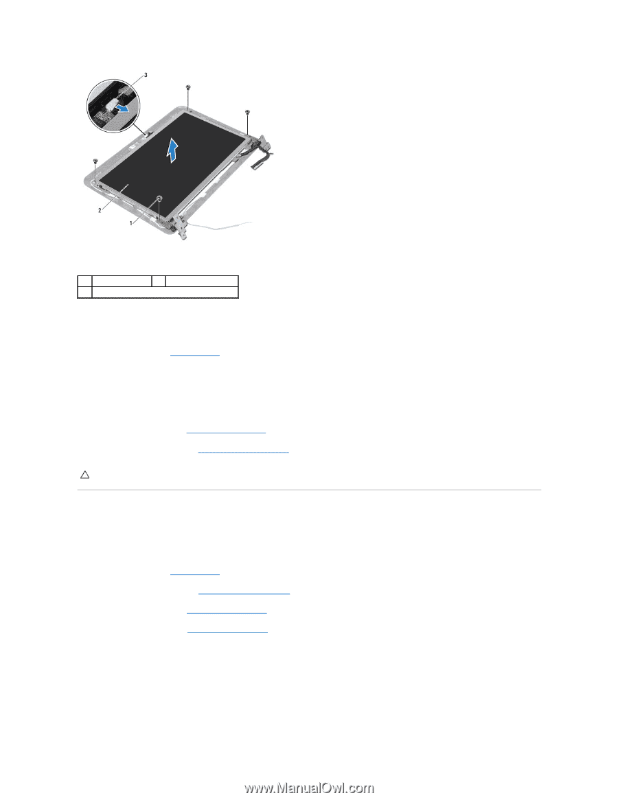
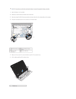
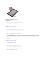
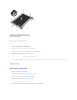
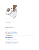
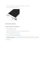
1 screws (4) 2 display panel 3 camera cable connector Replacing the Display Panel 1. Follow the instructions in Before You Begin. 2. Place the display panel over the display back cover. 3. Connect the camera cable to the connector on the camera module. 4. Replace the four screws that secure the display panel to the display back cover. 5. Replace the display bezel (see Replacing the Display Bezel). 6. Replace the display assembly (see Replacing the Display Assembly). CAUTION: Before turning on the computer, replace all screws and ensure that no stray screws remain inside the computer. Failure to do so may result in damage to the computer. Display Cable Removing the Display Cable 1. Follow the instructions in Before You Begin. 2. Remove the display assembly (see Removing the Display Assembly). 3. Remove the display bezel (see Removing the Display Bezel). 4. Remove the display panel (see Removing the Display Panel). 5. Turn the display panel over and place it on a clean surface. 6. Pull the pull-tab to disconnect the display cable from the connector on the display panel.
-
 1
1 -
2
-
3
-
4
-
5
-
6
-
7
-
8
-
9
-
 10
10 -
 11
11 -
 12
12 -
 13
13 -
 14
14 -
 15
15 -
 16
16 -
 17
17 -
 18
18 -
 19
19 -
 20
20 -
21
-
22
-
23
-
24
-
25
-
26
-
27
-
28
-
29
-
30
-
31
-
32
-
33
-
34
-
35
-
36
-
37
-
38
-
39
-
40
-
41
-
42
-
43
-
44
-
45
-
46
 |
 |