Dell Inspiron Mini 1018 Service Manual - Page 44
Replacing the System Board
 |
View all Dell Inspiron Mini 1018 manuals
Add to My Manuals
Save this manual to your list of manuals |
Page 44 highlights
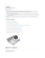
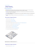
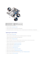
1 AC adapter cable connector 2 system board 3 I/O board cable connector 4 status lights board cable connector 5 I/O board cable grounding screw 6 screw 14. Remove the speaker (see Removing the Speaker). 15. Remove the screw that secures the system board to the computer base. 16. Carefully ease the connectors on the system board out of the slots in the computer base, and lift the system board out of the computer base. Replacing the System Board 1. Follow the instructions in Before You Begin. 2. Align the connectors on the system board with the slots on the computer base and place it on the computer base. 3. Replace the screw that secures the system board to the computer base. 4. Replace the speaker (see Replacing the Speaker). 5. Connect the AC adapter connector cable, status lights board cable, and I/O board cable to their connectors on the system board. 6. Replace the grounding screw that secures the I/O board cable to the system board. 7. Replace the support brackets (see Replacing the Support Brackets). 8. Replace the display assembly (see Replacing the Display Assembly). 9. Replace the middle cover (see Replacing the Middle Cover). 10. Replace the Mini-Card (see Replacing the Mini-Card). 11. Replace the memory module (see Replacing the Memory Module). 12. Replace the palm rest assembly (see Replacing the Palm Rest Assembly). 13. Replace the hard-drive assembly (follow the instructions from step 5 to step 7 in Replacing the Hard Drive). 14. Replace the keyboard (see Replacing the Keyboard).
-
 1
1 -
2
-
3
-
4
-
5
-
6
-
7
-
8
-
9
-
10
-
11
-
12
-
13
-
14
-
15
-
16
-
17
-
18
-
19
-
20
-
21
-
22
-
23
-
24
-
25
-
26
-
27
-
28
-
29
-
30
-
31
-
32
-
33
-
34
-
35
-
36
-
37
-
38
-
 39
39 -
 40
40 -
 41
41 -
 42
42 -
 43
43 -
 44
44 -
 45
45 -
 46
46
 |
 |
