Dell Precision 530 Microprocessor Replacement - Page 14
System Data, Removing the Microprocessor Heat Sink.
 |
View all Dell Precision 530 manuals
Add to My Manuals
Save this manual to your list of manuals |
Page 14 highlights
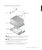
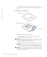
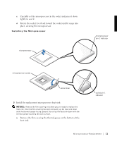
w w w.d el l.co m | su p po rt. d ell. com NOTICE: Carefully align the heat sink with the retention base before making contact with the base to help avoid spreading the thermal grease to other components. b Lower the heat sink to the microprocessor so that the heat sink fits in the heat sink retention base. c For each of the replacement metal clips that secure the heat sink to the microprocessor, fit the end of the clip that does not have the latch to the heat sink retention base. Then, press down on the clip's latch to secure the clip to the heat sink retention base (see "Removing the Microprocessor Heat Sink"). 6 Install the airflow shroud: a Insert the bottom anchor tabs of the shroud into the chassis anchor slots. b Press the shroud toward the chassis until the top anchor tabs on the shroud snap securely into place. See "Removing the Microprocessor Airflow Shroud." 7 Close the computer cover. 8 Stand the computer upright. 9 Reconnect the computer to the electrical outlet, and turn it on. NOTE: If enabled, the Chassis Intrusion option will cause the following message to be displayed at the next system start-up: ALERT! Cover was previously removed. 10 Enter system setup, and confirm that the correct microprocessor speed appears in the top left corner of the screen. Also, confirm that the top line in the System Data area correctly identifies the new microprocessor. 11 Exit system setup, turn off the computer, and attach the devices to the computer and electrical outlets. NOTE: For more information about system setup see your User's Guide. 12 M ic r op r o ce s s or Rep l a c em e n t
-
 1
1 -
2
-
3
-
4
-
5
-
6
-
7
-
8
-
 9
9 -
 10
10 -
 11
11 -
 12
12 -
 13
13 -
 14
14 -
 15
15 -
 16
16 -
 17
17 -
 18
18 -
 19
19 -
20
-
21
-
22
-
23
-
24
-
25
-
26
-
27
-
28
-
29
-
30
-
31
-
32
-
33
-
34
-
35
-
36
-
37
-
38
-
39
-
40
-
41
-
42
-
43
-
44
-
45
-
46
-
47
-
48
-
49
-
50
-
51
-
52
 |
 |