Dell Precision 530 Microprocessor Replacement - Page 8
Microprocessor Installation Guidelines - upgrade processor
 |
View all Dell Precision 530 manuals
Add to My Manuals
Save this manual to your list of manuals |
Page 8 highlights
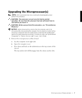
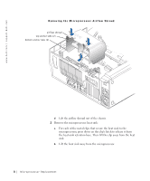
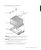
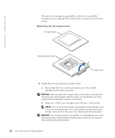
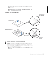
w w w.d el l.co m | su p po rt. d ell. com 4 Verify that the standby power light on the system board is not on. If it is on, you may need to wait 10 to 30 seconds for it to go out. Microprocessor Installation Guidelines • A voltage regulator module (VRM) must be installed for each microprocessor installed. To locate the VRM and microprocessor sockets, see "System Board Components" or "Interior Service Label" in your User's Guide. • For single-processor operations, the processor must be installed in socket 0 and the VRM must be installed in connector 0. Processor socket 1 and VRM connector 1 must be empty. To locate these components, see "System Board Components" or "Interior Service Label" in your User's Guide. • For dual-processor operations, both processor sockets and both VRM connectors must be populated. • For dual-processor operations, the two processors and the two VRMs must be identical. If the processors do not match, you receive a system message, the diagnostic lights indicate an error, and the computer may not start. If the VRMs do not match, the diagnostic lights will indicate an error. • If installing a Dell™ processor upgrade kit for either single or dual processors, remove and discard the original VRM(s). Then install the VRM(s) from the upgrade kit. If you are not installing a processor upgrade kit from Dell, reuse the original VRM(s). • If installing a Dell processor upgrade kit for either single or dual processors, remove and discard the original heat sink(s) and securing clips. Then install the heat sink(s) and securing clips from the upgrade kit. If you are not installing a processor upgrade kit from Dell, reuse the original heat sink(s) and securing clips. 6 Microprocessor Replacement
-
 1
1 -
2
-
 3
3 -
 4
4 -
 5
5 -
 6
6 -
 7
7 -
 8
8 -
 9
9 -
 10
10 -
 11
11 -
 12
12 -
 13
13 -
14
-
15
-
16
-
17
-
18
-
19
-
20
-
21
-
22
-
23
-
24
-
25
-
26
-
27
-
28
-
29
-
30
-
31
-
32
-
33
-
34
-
35
-
36
-
37
-
38
-
39
-
40
-
41
-
42
-
43
-
44
-
45
-
46
-
47
-
48
-
49
-
50
-
51
-
52
 |
 |