Dell Precision M6400 Service Manual
Dell Precision M6400 Manual
 |
View all Dell Precision M6400 manuals
Add to My Manuals
Save this manual to your list of manuals |
Dell Precision M6400 manual content summary:
- Dell Precision M6400 | Service Manual - Page 1
Dell Precision M6400 Service Manual Dell Precision™ M6400 Service Manual Troubleshooting Working on Your Computer Base Assembly Hard Drive Optical Drive WLAN/WiMax Card WWAN Card UWB WPAN Card and WPAN Card With Bluetooth®Wireless Technology Memory Coin-Cell Battery LED Cover Keyboard Edge-to-Edge - Dell Precision M6400 | Service Manual - Page 2
). If the problem persists, contact Dell Support. Memory failed to initialize or If two or more memory modules are installed, remove the modules (see Removing a Memory Module), then reinstall one module (see Replacing a Memory Module) and file:///T|/htdocs/systems/wsm6400/en/sm/trouble.htm[11/16 - Dell Precision M6400 | Service Manual - Page 3
occurred. System failed on hard drive initialization. System failed in Option ROM initialization. Contact Dell Support. Reseat the processor (see Processor Module). If the problem persists, contact Dell Support. Reseat any installed graphics cards. If available, install a working graphics card into - Dell Precision M6400 | Service Manual - Page 4
on using the system setup program, see the Dell™ Technology Guide at support.dell.com. The Dell Diagnostics is located on a separate diagnostic utility partition on your hard drive. NOTE: If the computer is connected to a docking device (docked), undock it. See the documentation that came with - Dell Precision M6400 | Service Manual - Page 5
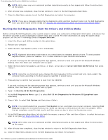
Troubleshooting: Dell Precision M6400 Service Manual NOTE: Write down any error codes and problem descriptions exactly as they appear and follow the instructions on the screen. 6. After all tests have completed, close the test window to return to the Dell Diagnostics Main Menu. 7. Close the Main - Dell Precision M6400 | Service Manual - Page 6
Troubleshooting: Dell Precision M6400 Service Manual 12. Remove the Drivers and Utilities media from the optical drive. Dell Diagnostics Main Menu After the Dell Diagnostics loads, the following menu appears: Option Function Test Memory Run the stand-alone memory test Test System Run system - Dell Precision M6400 | Service Manual - Page 7
Troubleshooting: Dell Precision M6400 Service Manual The Dell Diagnostics obtains configuration information for all devices from System Setup, memory, and various internal tests, and displays the information in the device list in the left pane of the screen. Parameters NOTE: The device list may - Dell Precision M6400 | Service Manual - Page 8
Troubleshooting: Dell Precision M6400 Service Manual If a peripheral device does not work, ensure that the device is properly connected. If an error message appears on the screen, write down the exact message. This message may help support personnel diagnose and fix the problem(s). If an error - Dell Precision M6400 | Service Manual - Page 9
. Turn off standby mode in Windows before writing to a disc - For information about setting power options, see the Dell™ Technology Guide at support.dell.com. You can also search for the keyword standby in Windows Help and Support for information on power management modes. Hard drive problems Run - Dell Precision M6400 | Service Manual - Page 10
Troubleshooting: Dell Precision M6400 Service Manual Ensure that the cable for the IEEE 1394 device is properly inserted into the device and into the connector on the computer Ensure that the IEEE 1394 device is enabled in system setup - For more information on using the system setup program, see - Dell Precision M6400 | Service Manual - Page 11
Troubleshooting: Dell Precision M6400 Service Manual 1. Press simultaneously to access the Task Manager. 2. Click the Applications tab. 3. Click to select the program that is no longer responding. 4. Click - Dell Precision M6400 | Service Manual - Page 12
Troubleshooting: Dell Precision M6400 Service Manual Back up your files immediately Use a virus-scanning program to check the hard drive, floppy disks, CDs, or DVDs Save and close any open files or programs and shut down your computer through the Start menu Memory Problems CAUTION: Before working - Dell Precision M6400 | Service Manual - Page 13
If you remove the card, store it in a safe and secure location. For information about your graphics card, go to support.dell.com. Check the diagnostic lights - See Diagnostic Lights. Check the display settings - See the Dell™ Technology Guide at support.dell.com. Adjust the Windows display settings - Dell Precision M6400 | Service Manual - Page 14
Troubleshooting: Dell Precision M6400 Service Manual Connect an external monitor - 1. Shut down your computer and connect an external monitor to the computer. 2. Turn on the computer and the monitor and adjust the monitor brightness and contrast controls. If the external monitor works, the computer - Dell Precision M6400 | Service Manual - Page 15
Your Computer: Dell Precision M6400 Service Manual Back to Contents Page Working on Your Computer Dell Precision™ M6400 Service Manual Recommended Tools Before Working on Your Computer After Working on Your Computer This document provides procedures for removing and installing the components - Dell Precision M6400 | Service Manual - Page 16
remove the battery. 1 battery 2 battery release latch 7. Disconnect any external devices and remove any cards before working on your computer: To remove a card, such as an ExpressCard, see the Dell™ Technology Guide at support.dell.com. To undock from a docking device, see the E-Port User's Guide - Dell Precision M6400 | Service Manual - Page 17
Your Computer: Dell Precision M6400 Service Manual 8. Turn the computer topside up, open the display, and press the power button to ground the system board. After Working on Your Computer After you have completed the replacement procedures, ensure you connect the external devices, cards, and cables - Dell Precision M6400 | Service Manual - Page 18
Base Assembly: Dell Precision M6400 Service Manual Back to Contents Page Base Assembly Dell Precision™ M6400 Service Manual Removing the Base Assembly Cover Replacing the Base Assembly Cover Removing the Base Assembly Replacing the Base Assembly CAUTION: Before working inside your computer, - Dell Precision M6400 | Service Manual - Page 19
Dell Precision M6400 Service Manual 3. Replace the M2 x 3-mm screws. 4. Follow the procedures in After Working on Your Computer. Removing the Base Assembly 1. Follow the procedures in Before Working on Your Computer. 2. Remove the base assembly cover (see Removing the Base Assembly Cover). 3. Remove - Dell Precision M6400 | Service Manual - Page 20
Base Assembly: Dell Precision M6400 Service Manual 12. Replace the optical drive (see Replacing the Optical Drive). 13. Replace the primary hard drive (see Replacing the Primary Hard Drive (HDD1)) and the secondary hard drive (see Replacing the Secondary Hard Drive (HDD2)). 14. Replace the base - Dell Precision M6400 | Service Manual - Page 21
Hard Drive Dell Precision™ M6400 Service Manual Removing the Primary Hard Drive (HDD1) Replacing the Primary Hard Drive (HDD1) Removing the Secondary Hard Drive (HDD2) Replacing the Secondary Hard Drive (HDD2) NOTE: Dell does not guarantee compatibility or provide support for hard drives - Dell Precision M6400 | Service Manual - Page 22
Hard Drive: Dell Precision M6400 Service Manual 1 HDD1 2 pull tab 6. Remove the two M3 x 3-mm screws that secure the pull tab to the HDD1. 7. Set the pull tab aside to use with the replacement HDD1. 1 HDD1 2 M3 x 3-mm screws (2) 3 pull tab Replacing the Primary Hard Drive (HDD1) CAUTION: Before - Dell Precision M6400 | Service Manual - Page 23
Hard Drive: Dell Precision M6400 Service Manual 2. Place the HDD1 in the computer, and slide the HDD1 into the connector on the system board. 3. Replace the cover on the HDD1 and tighten the two captive screws. 4. Replace the base assembly cover (see Replacing the Base Assembly Cover). 5. Follow the - Dell Precision M6400 | Service Manual - Page 24
Hard Drive: Dell Precision M6400 Service Manual 7. Remove the interposer from the HDD2 or the place-holder, and set the interposer aside. Replacing the Secondary Hard Drive (HDD2) CAUTION: Before working inside your computer, read the safety information that shipped with your computer. For - Dell Precision M6400 | Service Manual - Page 25
Optical Drive: Dell Precision M6400 Service Manual Back to Contents Page Optical Drive Dell Precision™ M6400 Service Manual Removing the Optical Drive Replacing the Optical Drive Removing the Optical Drive CAUTION: Before working inside your computer, read the safety information that shipped - Dell Precision M6400 | Service Manual - Page 26
Optical Drive: Dell Precision M6400 Service Manual 1. Slide the optical drive into the media bay. 2. Replace the M2.5 x 8-mm screw. 3. Follow the procedures in After Working on Your Computer. Back to Contents Page file:///T|/htdocs/systems/wsm6400/en/sm/optical.htm[11/16/2012 10:26:28 AM] - Dell Precision M6400 | Service Manual - Page 27
WLAN/WiMax Card: Dell Precision M6400 Service Manual Back to Contents Page WLAN/WiMax Card Dell Precision™ M6400 Service Manual Removing the WLAN/WiMax Card Replacing the WLAN/WiMax Card CAUTION: Before working inside your computer, read the safety information that shipped with your computer. - Dell Precision M6400 | Service Manual - Page 28
WLAN/WiMax Card: Dell Precision M6400 Service Manual 1 WLAN/WiMax card 2 card connector Replacing the WLAN/WiMax Card NOTICE: The connectors are keyed to ensure correct insertion. If you feel resistance, check the connectors on the card and on the system board, and realign the card. NOTICE: To - Dell Precision M6400 | Service Manual - Page 29
WWAN Card: Dell Precision M6400 Service Manual Back to Contents Page WWAN Card Dell Precision™ M6400 Service Manual Removing a WWAN Card Replacing a WWAN Card CAUTION: Before working inside your computer, read the safety information that shipped with your computer. For additional safety best - Dell Precision M6400 | Service Manual - Page 30
WWAN Card: Dell Precision M6400 Service Manual 1 WWAN card 2 card connector Replacing a WWAN Card NOTICE: The connectors are keyed to ensure correct insertion. If you feel resistance, check the connectors on the card and on the system board, and realign the card. NOTICE: To avoid damage to the - Dell Precision M6400 | Service Manual - Page 31
UWB WPAN Card and WPAN Card With Bluetooth®Wireless Technology: Dell Precision M6400 Service Manual Back to Contents Page UWB WPAN Card and WPAN Card With Bluetooth®Wireless Technology Dell Precision™ M6400 Service Manual Removing a WPAN Card Replacing a WPAN Card CAUTION: Before working inside - Dell Precision M6400 | Service Manual - Page 32
UWB WPAN Card and WPAN Card With Bluetooth®Wireless Technology: Dell Precision M6400 Service Manual 1 WPAN card 2 card connector Replacing a WPAN Card NOTICE: The connectors are keyed to ensure correct insertion. If you feel resistance, check the connectors on the card and on the system board, - Dell Precision M6400 | Service Manual - Page 33
M6400 Service Manual Back to Contents Page Memory Dell Precision™ M6400 Service Manual Removing a Memory Module Replacing a Memory Module Your computer has four user-accessible SODIMM sockets: DIMM A and DIMM B are located under the keyboard; DIMM C and DIMM D are located under the base - Dell Precision M6400 | Service Manual - Page 34
Memory: Dell Precision M6400 Service Manual 1 memory module 3 DIMM A and DIMM B 2 securing clips (2) 4 DIMM C and DIMM D Replacing a Memory Module CAUTION: Before working inside your computer, read the safety information that shipped with your computer. For additional safety best practices - Dell Precision M6400 | Service Manual - Page 35
Memory: Dell Precision M6400 Service Manual 1 tab 3 DIMM A and DIMM B 2 notch 4 DIMM C and DIMM D 3. To replace DIMM A or DIMM B: a. Replace the keyboard (see Replacing the Keyboard). b. Replace the LED cover (see Replacing the LED Cover). 4. To replace DIMM C or DIMM D: a. Replace the base - Dell Precision M6400 | Service Manual - Page 36
Coin-Cell Battery: Dell Precision M6400 Service Manual Back to Contents Page Coin-Cell Battery Dell Precision™ M6400 Service Manual Removing the Coin-Cell Battery Replacing the Coin-Cell Battery Removing the Coin-Cell Battery CAUTION: Before working inside your computer, read the safety - Dell Precision M6400 | Service Manual - Page 37
Coin-Cell Battery: Dell Precision M6400 Service Manual 1 coin-cell battery 2 coin-cell battery cable 3. Replace the base assembly cover (see Replacing the Base Assembly Cover). 4. Follow the procedures in After Working on Your Computer. Back to Contents Page file:///T|/htdocs/systems/wsm6400/en - Dell Precision M6400 | Service Manual - Page 38
LED Cover: Dell Precision M6400 Service Manual Back to Contents Page LED Cover Dell Precision™ M6400 Service Manual Removing the LED Cover Replacing the LED Cover Removing the LED Cover CAUTION: Before working inside your computer, read the safety information that shipped with your computer. For - Dell Precision M6400 | Service Manual - Page 39
LED Cover: Dell Precision M6400 Service Manual Back to Contents Page file:///T|/htdocs/systems/wsm6400/en/sm/ledcvr.htm[11/16/2012 10:26:45 AM] - Dell Precision M6400 | Service Manual - Page 40
Keyboard: Dell Precision M6400 Service Manual Back to Contents Page Keyboard Dell Precision™ M6400 Service Manual Removing the Keyboard Replacing the Keyboard Removing the Keyboard on www.dell.com at: www.dell.com/regulatory_compliance. file:///T|/htdocs/systems/wsm6400/en/sm/keyboard.htm[11/ - Dell Precision M6400 | Service Manual - Page 41
Dell Precision M6400 Service Manual NOTICE: The key caps on the keyboard are fragile, easily dislodged, and time- consuming to replace. Exercise care when removing and handling the keyboard. 1. Align the notch on the center metal pull tab with the alignment tab on the computer. 2. Slide the keyboard - Dell Precision M6400 | Service Manual - Page 42
Edge-to-Edge Display: Dell Precision M6400 Service Manual Back to Contents Page Edge-to-Edge Display Dell Precision™ M6400 Service Manual Removing the Edge-to-Edge Display Replacing the Edge-to-Edge Display Removing the Edge-to-Edge Display CAUTION: Before working inside your computer, read the - Dell Precision M6400 | Service Manual - Page 43
Edge-to-Edge Display: Dell Precision M6400 Service Manual 1 M2.5 x 5-mm screws (2) on left hinge 2 M2.5 x 5-mm screws (2) on right hinge 9. Pull the wireless antenna cables up through the computer. 10. Remove the LVDS captive screw. 11. Disconnect and unroute the display cable. 12. Disconnect and - Dell Precision M6400 | Service Manual - Page 44
-Edge Display: Dell Precision M6400 Service Manual Replacing the Edge-to-Edge Display CAUTION: Before working inside your computer, read the safety information that shipped with your computer. For additional safety best practices information, see the Regulatory Compliance Homepage on www.dell.com at - Dell Precision M6400 | Service Manual - Page 45
Displays Dell Precision™ M6400 Service Manual Removing the Display Bezel Replacing the Display Bezel Removing the Display Panel Replacing the Display Panel Removing the Inverter Board (CCFL Display Only) Replacing the Inverter Board (CCFL Display Only) Removing the Microphone/Camera - Dell Precision M6400 | Service Manual - Page 46
Dell Precision M6400 Service Manual 1 left side of bezel 2 top of bezel 3 right side of bezel 4 M2.5 x 5-mm screws (2) 5 display assembly 6 bottom of bezel Replacing bezel into place. 4. Replace the two M2.5 x 5-mm screws on the bottom of the bezel. file:///T|/htdocs/systems/wsm6400/en/sm/displayb. - Dell Precision M6400 | Service Manual - Page 47
LED and CCFL Displays: Dell Precision M6400 Service Manual 1 display bezel 2 M2.5 x 5-mm screws (2) 3 hinges 4 display cover 5. Follow the procedures in After Working on Your Computer. Removing the Display Panel CAUTION: Before working inside your computer, read the safety information that - Dell Precision M6400 | Service Manual - Page 48
LED and CCFL Displays: Dell Precision M6400 Service Manual 1 M2 x 3-mm screws (8) 2 display panel 3 M2 x 3-mm screws (2) 4 bracket 5 antenna cables 5 display cover the release tabs together to disconnect the cables. file:///T|/htdocs/systems/wsm6400/en/sm/displayb.htm[11/16/2012 10:27:02 AM] - Dell Precision M6400 | Service Manual - Page 49
Displays: Dell Precision M6400 Service Manual 1 underside of display panel 2 cables (2) 3 cable connector 4 cable connector 5 release tabs 7. Remove two M2 x 3-mm screws along the top of the panel to remove the bracket. 1 display panel 2 M2 x 3-mm screws (2) 3 bracket Replacing the Display - Dell Precision M6400 | Service Manual - Page 50
LED and CCFL Displays: Dell Precision M6400 Service Manual two in the bracket along the top of the display panel. 5. Replace the display bezel (see Replacing the Display Bezel). 6. Follow the procedures in After Working on Your Computer. Removing the Inverter Board (CCFL Display Only) CAUTION: - Dell Precision M6400 | Service Manual - Page 51
LED and CCFL Displays: Dell Precision M6400 Service Manual 5. Follow the procedures in After Working on Your Computer. Removing the Microphone/Camera Board CAUTION: Before working inside your computer, read the safety information that shipped with your computer. For additional safety best practices - Dell Precision M6400 | Service Manual - Page 52
LED and CCFL Displays: Dell Precision M6400 Service Manual 5. Follow the procedures in After Working on Your Computer. Removing the Display Assembly CAUTION: Before working inside your computer, read the safety information that shipped with your computer. For additional safety best practices - Dell Precision M6400 | Service Manual - Page 53
LED and CCFL Displays: Dell Precision M6400 Service Manual 1 M2.5 x 5-mm screws (2) on left hinge 2 M2.5 x 5-mm screws (2) on right hinge 9. Pull the wireless antenna cables up through the computer. 10. Remove the LVDS captive screw. 11. Disconnect and unroute the display cable. 12. Disconnect and - Dell Precision M6400 | Service Manual - Page 54
Displays: Dell Precision M6400 Service Manual 5. Replace the LVDS captive screw. 6. Thread the WWAN, WLAN, and WPAN antenna cables through the computer. 7. Replace the keyboard (see Replacing the Keyboard). 8. Replace the LED cover (see Replacing the LED Cover). 9. Close the display and turn the - Dell Precision M6400 | Service Manual - Page 55
LED and CCFL Displays: Dell Precision M6400 Service Manual Back to Contents Page file:///T|/htdocs/systems/wsm6400/en/sm/displayb.htm[11/16/2012 10:27:02 AM] - Dell Precision M6400 | Service Manual - Page 56
Palm Rest Assembly: Dell Precision M6400 Service Manual Back to Contents Page Palm Rest Assembly Dell Precision™ M6400 Service Manual Removing the Palm Rest Assembly Replacing the Palm Rest Assembly Removing the Palm Rest Assembly CAUTION: Before working inside your computer, read the safety - Dell Precision M6400 | Service Manual - Page 57
Palm Rest Assembly: Dell Precision M6400 Service Manual 1 2 x 3-mm screws (9) 10. Disconnect the biometer, speaker, touch pad, contactless smart card, and power cables from the system board. NOTICE: Do not use force to separate the palm rest from the computer. If you encounter resistance, gently - Dell Precision M6400 | Service Manual - Page 58
rest to the base assembly. 2. Connect the biometer, contactless smart card, touchpad, speaker, and power cables to the system board. 3. Replace the nine M2 x 3-mm screws in the holes labeled "P". 4. Replace the keyboard (see Replacing the Keyboard). 5. Replace the LED cover (see Replacing the LED - Dell Precision M6400 | Service Manual - Page 59
Fan: Dell Precision M6400 Service Manual Back to Contents Page Fan Dell Precision™ M6400 Service Manual Removing the Fan Replacing the Fan Removing the Fan CAUTION: Before working inside your computer, read the safety information that shipped with your computer. For additional safety best - Dell Precision M6400 | Service Manual - Page 60
Fan: Dell Precision M6400 Service Manual 3 fan cable Replacing the Fan CAUTION: Before working inside your computer, read the safety information that shipped with your computer. For additional safety best practices information, see the Regulatory Compliance Homepage on www.dell.com at: www.dell.com/ - Dell Precision M6400 | Service Manual - Page 61
Heatsink Assembly: Dell Precision M6400 Service Manual Back to Contents Page Processor Heatsink Assembly Dell Precision™ M6400 Service Manual Removing the Processor Heatsink Assembly Replacing the Processor Heatsink Assembly Removing the Processor Heatsink Assembly CAUTION: Before working - Dell Precision M6400 | Service Manual - Page 62
Assembly: Dell Precision M6400 Service Manual Replacing the Processor Heatsink Assembly CAUTION: Before working inside your computer, read the safety information that shipped with your computer. For additional safety best practices information, see the Regulatory Compliance Homepage on www.dell.com - Dell Precision M6400 | Service Manual - Page 63
Video Card/Heatsink Assembly: Dell Precision M6400 Service Manual Back to Contents Page Video Card/Heatsink Assembly Dell Precision™ M6400 Service Manual Removing the Video Card/Heatsink Assembly Replacing the Video Card/Heatsink Assembly Removing the Video Card/Heatsink Assembly CAUTION: Before - Dell Precision M6400 | Service Manual - Page 64
Video Card/Heatsink Assembly: Dell Precision M6400 Service Manual 1 video card/heatsink assembly 2 captive screws (3) 3 fan cable Replacing the Video Card/Heatsink Assembly CAUTION: Before working inside your computer, read the safety information that shipped with your computer. For additional - Dell Precision M6400 | Service Manual - Page 65
Processor Module: Dell Precision M6400 Service Manual Back to Contents Page Processor Module Dell Precision™ M6400 Service Manual Removing the Processor Module Replacing the Processor Module Removing the Processor Module CAUTION: Before working inside your computer, read the safety information - Dell Precision M6400 | Service Manual - Page 66
Processor Module: Dell Precision M6400 Service Manual until it comes to the cam stop. 1 ZIF socket 2 ZIF-socket cam screw NOTICE: To ensure maximum cooling for the processor, do not touch the heat transfer areas on the processor heatsink assembly. The oils in your skin can reduce the heat transfer - Dell Precision M6400 | Service Manual - Page 67
10. Replace the secondary hard drive (see Replacing the Secondary Hard Drive (HDD2)). 11. Replace the base assembly cover (see Replacing the Base Assembly Cover). 12. Follow the procedures in After Working on Your Computer. Back to Contents Page file:///T|/htdocs/systems/wsm6400/en/sm/cpu.htm[11 - Dell Precision M6400 | Service Manual - Page 68
Card Cage: Dell Precision M6400 Service Manual Back to Contents Page Card Cage Dell Precision™ M6400 Service Manual Removing the Card Cage Replacing the Card Cage Removing the Card Cage CAUTION: Before working inside your computer, read the safety information that shipped with your computer. For - Dell Precision M6400 | Service Manual - Page 69
Card Cage: Dell Precision M6400 Service Manual Replacing the Card Cage CAUTION: Before working inside your computer, read the safety information that shipped with your computer. For additional safety best practices information, see the Regulatory Compliance Homepage on www.dell.com at: www.dell.com/ - Dell Precision M6400 | Service Manual - Page 70
IEEE 1394 Card: Dell Precision M6400 Service Manual Back to Contents Page IEEE 1394 Card Dell Precision™ M6400 Service Manual Removing the IEEE 1394 Card Replacing the IEEE 1394 Card Removing the IEEE 1394 Card CAUTION: Before working inside your computer, read the safety information that - Dell Precision M6400 | Service Manual - Page 71
1394 Card: Dell Precision M6400 Service Manual computer. For additional safety best practices information, see the Regulatory Compliance Homepage on www.dell.com at: www.dell.com/regulatory_compliance. 1. Place the IEEE 1394 card in at an angle to fit the connector into the base assembly. 2. Replace - Dell Precision M6400 | Service Manual - Page 72
Left I/O Board: Dell Precision M6400 Service Manual Back to Contents Page Left I/O Board Dell Precision™ M6400 Service Manual Removing the Left I/O Board Replacing the Left I/O Board Removing the Left I/O Board CAUTION: Before working inside your computer, read the safety information that - Dell Precision M6400 | Service Manual - Page 73
Board: Dell Precision M6400 Service Manual Replacing the Left I/O Board CAUTION: Before working inside your computer, read the safety information that shipped with your computer. For additional safety best practices information, see the Regulatory Compliance Homepage on www.dell.com at: www.dell.com - Dell Precision M6400 | Service Manual - Page 74
Right I/O Board: Dell Precision M6400 Service Manual Back to Contents Page Right I/O Board Dell Precision™ M6400 Service Manual Removing the Right I/O Board Replacing the Right I/O Board Removing the Right I/O Board CAUTION: Before working inside your computer, read the safety information that - Dell Precision M6400 | Service Manual - Page 75
: Dell Precision M6400 Service Manual 5 right I/O board Replacing the Right I/O Board CAUTION: Before working inside your computer, read the safety information that shipped with your computer. For additional safety best practices information, see the Regulatory Compliance Homepage on www.dell.com - Dell Precision M6400 | Service Manual - Page 76
System Board: Dell Precision M6400 Service Manual Back to Contents Page System Board Dell Precision™ M6400 Service Manual Removing the System Board Replacing the System Board The system board's BIOS chip contains the Service Tag, which is also visible on a barcode label on the bottom of the - Dell Precision M6400 | Service Manual - Page 77
System Board: Dell Precision M6400 Service Manual 23. Remove the two M2.5 x 8-mm screws from the bracket and remove the bracket. 1 M2.5 x 8-mm screws (2) 2 system board 3 M2.5 x 5-mm screws (8) 4 bracket 24. Lift the system board out of the base assembly. Replacing the System Board CAUTION: Before - Dell Precision M6400 | Service Manual - Page 78
System Board: Dell Precision M6400 Service Manual 4. Replace the right I/O board (see Replacing the Right I/O Board). 5. Replace the left I/O board (see Replacing the Left I/O Board). 6. Replace the card cage (see Replacing the Card Cage). 7. Replace the processor (see Replacing the Processor Module - Dell Precision M6400 | Service Manual - Page 79
Flashing the BIOS: Dell Precision M6400 Service Manual Back to Contents Page Flashing the BIOS Dell Precision™ M6400 Service Manual Flashing the BIOS From a CD Flashing the BIOS From the Hard Drive If a BIOS-update program CD is provided with a new system board, flash the BIOS from the CD. If - Dell Precision M6400 | Service Manual - Page 80
: Dell Precision M6400 Service Manual The file downloads to your desktop. 8. Click Close if the Download Complete window appears. The file icon appears on your desktop and is titled the same as the downloaded BIOS update file. 9. Double-click the file icon on the desktop and follow the instructions - Dell Precision M6400 | Service Manual - Page 81
Biometer Cable: Dell Precision M6400 Service Manual Back to Contents Page Biometer Cable Dell Precision™ M6400 Service Manual Removing the Biometer Cable Replacing the Biometer Cable Removing the Biometer Cable CAUTION: Before working inside your computer, read the safety information that
-
 1
1 -
 2
2 -
 3
3 -
 4
4 -
 5
5 -
 6
6 -
 7
7 -
8
-
9
-
10
-
11
-
12
-
13
-
14
-
15
-
16
-
17
-
18
-
19
-
20
-
21
-
22
-
23
-
24
-
25
-
26
-
27
-
28
-
29
-
30
-
31
-
32
-
33
-
34
-
35
-
36
-
37
-
38
-
39
-
40
-
41
-
42
-
43
-
44
-
45
-
46
-
47
-
48
-
49
-
50
-
51
-
52
-
53
-
54
-
55
-
56
-
57
-
58
-
59
-
60
-
61
-
62
-
63
-
64
-
65
-
66
-
67
-
68
-
69
-
70
-
71
-
72
-
73
-
74
-
75
-
76
-
77
-
78
-
79
-
80
-
81
 |
 |

Dell Precision M6400 Service Manual
file:///T|/htdocs/systems/wsm6400/en/sm/index.htm[11/16/2012 10:26:08 AM]
Dell Precision™ M6400 Service Manual
Troubleshooting
Working on Your Computer
Base Assembly
Hard Drive
Optical Drive
WLAN/WiMax Card
WWAN Card
UWB WPAN Card and WPAN Card With Bluetooth®Wireless
Technology
Memory
Coin-Cell Battery
LED Cover
Keyboard
Edge-to-Edge Display
LED and CCFL Displays
Palm Rest Assembly
Fan
Processor Heatsink Assembly
Video Card/Heatsink
Assembly
Processor Module
Card Cage
IEEE 1394 Card
Left I/O Board
Right I/O Board
System Board
Flashing the BIOS
Biometer Cable
Model PP08X
Notes, Notices, and Cautions
NOTE:
A NOTE indicates important information that helps you make better use of your computer.
NOTICE:
A NOTICE indicates either potential damage to hardware or loss of data and tells you how to
avoid the problem.
CAUTION:
A CAUTION indicates potential for property damage, personal injury, or death.
If you purchased a DELL™ n Series computer, any references in this document to Microsoft
®
Windows
®
operating systems
are not applicable.
Information in this document is subject to change without notice.
© 2008 Dell Inc. All rights reserved.
Reproduction of these materials in any manner whatsoever without the written permission of Dell Inc. is strictly forbidden.
Trademarks used in this text:
Dell,
the
DELL
logo, and
Dell Precision
are trademarks of Dell Inc.;
Bluetooth
is a registered trademark owned by
Bluetooth SIG, Inc., and is used by Dell under license;
Microsoft, Windows, Windows Vista,
and the
Windows Vista
start button logo are either
trademarks or registered trademarks of Microsoft Corporation in the United States and/or other countries.
Other trademarks and trade names may be used in this document to refer to either the entities claiming the marks and names or their products.
Dell Inc. disclaims any proprietary interest in trademarks and trade names other than its own.
September 2009
Rev. A01