Dell Vostro 1014 Service Manual
Dell Vostro 1014 Manual
 |
View all Dell Vostro 1014 manuals
Add to My Manuals
Save this manual to your list of manuals |
Dell Vostro 1014 manual content summary:
- Dell Vostro 1014 | Service Manual - Page 1
Dell™ Vostro™ 1014/1015 Service Manual Working on Your Computer Adding and Replacing Parts Specifications Diagnostics System Setup Notes, Cautions, and Warnings NOTE: A NOTE indicates important information that helps you make better use of your computer. CAUTION: A CAUTION indicates potential damage - Dell Vostro 1014 | Service Manual - Page 2
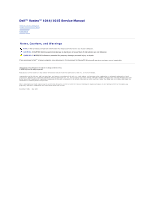
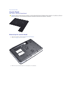
Page Access Panel Dell™ Vostro™ 1014/1015 Service Manual WARNING: Before working inside your computer, read the safety information that shipped with your computer. For additional safety best practices information, see the Regulatory Compliance Homepage at www.dell.com/regulatory_compliance. Removing - Dell Vostro 1014 | Service Manual - Page 3
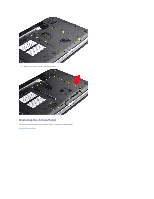
4. Remove the access panel from the computer. Replacing the Access Panel Perform the above steps in the reverse order to replace the access panel. Back to Contents Page - Dell Vostro 1014 | Service Manual - Page 4
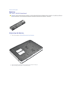
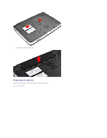
to Contents Page Battery Dell™ Vostro™ 1014/1015 Service Manual WARNING: Before working inside your computer, read the safety information that shipped with your computer. For additional safety best practices information, see the Regulatory Compliance Homepage at www.dell.com/regulatory_compliance - Dell Vostro 1014 | Service Manual - Page 5
3. Lift the battery from the computer. Replacing the Battery Perform the above steps in the reverse order to replace the battery. Back to Contents Page - Dell Vostro 1014 | Service Manual - Page 6
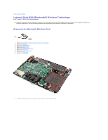
Back to Contents Page Internal Card With Bluetooth® Wireless Technology Dell™ Vostro™ 1014/1015 Service Manual WARNING: Before working inside your computer, read the safety information that shipped with your computer. For additional safety best practices information, see the Regulatory Compliance - Dell Vostro 1014 | Service Manual - Page 7
12. Release the Bluetooth card cable from its routing groove and lift the Bluetooth card to remove it from the computer. Replacing the Bluetooth Card Perform the above steps in the reverse order to replace the Bluetooth card. Back to Contents Page - Dell Vostro 1014 | Service Manual - Page 8
Page Coin-Cell Battery Dell™ Vostro™ 1014/1015 Service Manual WARNING: Before working inside your computer, read the safety information that shipped with your computer. For additional safety best practices information, see the Regulatory Compliance Homepage at www.dell.com/regulatory_compliance - Dell Vostro 1014 | Service Manual - Page 9
11. Disconnect the coin-cell battery cable from the connector on the system board, then lift the coin-cell battery to remove it from the computer. Replacing the Coin-Cell Battery Perform the above steps in the reverse order to replace the coin-cell battery. Back to Contents Page - Dell Vostro 1014 | Service Manual - Page 10
™ Vostro™ 1014/1015 Service Manual WARNING: Before working inside your computer, read the safety information that shipped with your computer. For additional safety best practices information, see the Regulatory Compliance Homepage at www.dell.com/regulatory_compliance. Vostro 1014 Vostro 1015 Vostro - Dell Vostro 1014 | Service Manual - Page 11
5. Turn the computer over and open the display. 6. Remove the control panel cover from the computer. Replacing the Control Panel Cover Perform the above steps in the reverse order to replace the control panel cover. Vostro 1015 Removing the Control Panel Cover 1. Follow the procedures in Before - Dell Vostro 1014 | Service Manual - Page 12
3. Remove the eight control panel cover screws from the bottom of the computer. 4. Turn the computer over and open the display. 5. Remove the control panel cover from the computer. Replacing the Control Panel Cover - Dell Vostro 1014 | Service Manual - Page 13
Perform the above steps in the reverse to replace the control panel cover. Back to Contents Page - Dell Vostro 1014 | Service Manual - Page 14
Inside Your Computer. 2. Remove the battery. 3. Remove the access panel. 4. Remove the hard drive. 5. Remove the WLAN card. 6. Remove the control panel cover. 7. Remove the keyboard. 8. Remove the display assembly. 9. Remove the palm rest. 10. Disconnect the processor fan cable from the connector on - Dell Vostro 1014 | Service Manual - Page 15
11. Remove the screw that secures the processor fan to the computer. 12. Lift the processor fan from the computer. - Dell Vostro 1014 | Service Manual - Page 16
Replacing the Processor Fan Perform the above steps in the reverse order to replace the processor fan. Back to Contents Page - Dell Vostro 1014 | Service Manual - Page 17
Contents Page ExpressCard Dell™ Vostro™ 1014/1015 Service Manual WARNING: Before working inside your computer, read the safety information that shipped with your computer. For additional safety best practices information, see the Regulatory Compliance Homepage at www.dell.com/regulatory_compliance - Dell Vostro 1014 | Service Manual - Page 18
Replacing the ExpressCard Perform the above steps in the reverse order to replace the ExpressCard. Back to Contents Page - Dell Vostro 1014 | Service Manual - Page 19
/1015 Service Manual WARNING: Before working inside your computer, read the safety information that shipped with your computer. For additional safety best practices information, see the Regulatory Compliance Homepage at www.dell.com/regulatory_compliance. Removing the Hard Drive Assembly Replacing - Dell Vostro 1014 | Service Manual - Page 20
6. Lift the hard drive assembly from the computer. Replacing the Hard Drive Assembly Perform the above steps in the reverse order to replace the hard drive assembly in the computer. Removing the Hard Drive Bracket 1. Follow the procedures in Before Working Inside Your Computer. 2. Remove the battery - Dell Vostro 1014 | Service Manual - Page 21
5. Remove the four screws, two on either sides of the bracket, that secure the hard drive to the hard drive bracket. 6. Lift the bracket from the hard drive. Replacing the Hard Drive Bracket - Dell Vostro 1014 | Service Manual - Page 22
Your Computer. 2. Remove the battery. 3. Remove the access panel. 4. Remove the hard drive. 5. Tugging gently, remove the hard drive interposer from the hard drive. Replacing the Hard Drive Interposer Perform the above steps in the reverse order to replace the hard drive interposer. Back to Contents - Dell Vostro 1014 | Service Manual - Page 23
. 6. Remove the hard drive. 7. Remove the memory modules. 8. Remove the WLAN card. 9. Remove the control panel cover. 10. Remove the keyboard. 11. Remove the display assembly. 12. Remove the palm rest. 13. Remove the processor fan. 14. Remove the I/O board. 15. Remove the Bluetooth wireless card. 16 - Dell Vostro 1014 | Service Manual - Page 24
18. Remove the heat sink from the system board. Replacing the Heat Sink Perform the above steps in the reverse order to replace the heat sink. Back to Contents Page - Dell Vostro 1014 | Service Manual - Page 25
the procedures in Before Working Inside Your Computer. 2. Remove the battery. 3. Remove the access panel. 4. Remove the hard drive. 5. Remove the WLAN card. 6. Remove the control panel cover. 7. Remove the keyboard. 8. Remove the display assembly. 9. Remove the palm rest. 10. Remove the two screws - Dell Vostro 1014 | Service Manual - Page 26
11. Disconnect the modem cable from the connector on the I/O board. 12. Lift the I/O board to remove it from the computer. Replacing the I/O Board Perform the above steps in the reverse order to replace the I/O board. Back to Contents Page - Dell Vostro 1014 | Service Manual - Page 27
to Contents Page Keyboard Dell™ Vostro™ 1014/1015 Service Manual WARNING: Before working inside your computer, read the safety information that shipped with your computer. For additional safety best practices information, see the Regulatory Compliance Homepage at www.dell.com/regulatory_compliance - Dell Vostro 1014 | Service Manual - Page 28
NOTE: Lift the keyboard carefully to ensure that you do not pull on the keyboard cable. 6. Rotate the keyboard data clip to release the keyboard cable from the connector on the system board. 7. Remove the keyboard from the computer. - Dell Vostro 1014 | Service Manual - Page 29
Replacing the Keyboard Perform the above steps in the reverse order to replace the keyboard. Back to Contents Page - Dell Vostro 1014 | Service Manual - Page 30
Replacing the Display Camera Removing the Display Inverter Cable Replacing the Display Inverter Cable Removing the Display Assembly 1. Follow the procedures in Before Working Inside Your Computer. 2. Remove the battery. 3. Remove the access panel. 4. Remove the hard drive. 5. Remove the WLAN card - Dell Vostro 1014 | Service Manual - Page 31
9. Remove the two screws that secure the display assembly to the bottom of the base of the computer. 10. Turn the computer right-side up and open the display. 11. Remove the wireless cable from the routing guides. - Dell Vostro 1014 | Service Manual - Page 32
12. Rotate the display inverter cable clip to disconnect the display inverter cable. 13. Remove the two screws that secure the display assembly to the top of the base of the computer. 14. Lift the display assembly from the computer. Ensure that all the cables are carefully removed away from the - Dell Vostro 1014 | Service Manual - Page 33
steps in the reverse order to replace the display assembly. Removing the Display Bezel 1. Follow the procedures in Before Working Inside Your Computer. 2. Remove the battery. 3. Remove the access panel. 4. Remove the hard drive. 5. Remove the WLAN card. 6. Remove the control panel cover. 7. Remove - Dell Vostro 1014 | Service Manual - Page 34
9. Using a plastic scribe, remove the six rubber screw covers from the display assembly. 10. Remove the six screws from the display assembly. - Dell Vostro 1014 | Service Manual - Page 35
the reverse order to replace the display bezel into the display assembly. Removing the Display LED Panel 1. Follow the procedures in Before Working Inside Your Computer. 2. Remove the battery. 3. Remove the access panel. 4. Remove the hard drive. 5. Remove the WLAN card. 6. Remove the control panel - Dell Vostro 1014 | Service Manual - Page 36
8. Remove the display assembly. 9. Remove the display bezel. 10. Remove the four screws that secure the display panel to the display assembly. 11. Disconnect the display camera cable. - Dell Vostro 1014 | Service Manual - Page 37
above steps in the reverse to replace the display LED panel. Removing the Display Camera 1. Follow the procedures in Before Working Inside Your Computer. 2. Remove the battery. 3. Remove the access panel. 4. Remove the hard drive. 5. Remove the WLAN card. 6. Remove the control panel cover. 7. Remove - Dell Vostro 1014 | Service Manual - Page 38
to replace the display camera into its bracket, and from there to the display assembly. Removing the Display Inverter Cable 1. Follow the procedures in Before Working Inside Your Computer. 2. Remove the battery. 3. Remove the access panel. 4. Remove the hard drive. 5. Remove the WLAN card. 6. Remove - Dell Vostro 1014 | Service Manual - Page 39
the two screws that secure the display camera to the display LED panel. 12. Carefully detach and remove the display inverter cable from the display LED panel. Replacing the Display Inverter Cable Perform the above steps in the reverse order to replace the display inverter cable. Back to Contents - Dell Vostro 1014 | Service Manual - Page 40
. 6. Remove the hard drive. 7. Remove the memory modules. 8. Remove the WLAN card. 9. Remove the control panel cover. 10. Remove the keyboard. 11. Remove the display assembly. 12. Remove the palm rest. 13. Remove the processor fan. 14. Remove the I/O board. 15. Remove the Bluetooth wireless card. 16 - Dell Vostro 1014 | Service Manual - Page 41
17. Disconnect the power cable from the system board. 18. Remove the five screws that secure the system board to the computer chassis. - Dell Vostro 1014 | Service Manual - Page 42
19. Lift the system board up and away from the computer chassis. Replacing the System Board Perform the above steps in the reverse order to replace the system board. Vostro 1015 Removing the System Board 1. Follow the procedures in Before Working Inside Your Computer. - Dell Vostro 1014 | Service Manual - Page 43
. 6. Remove the hard drive. 7. Remove the memory modules. 8. Remove the WLAN card. 9. Remove the control panel cover. 10. Remove the keyboard. 11. Remove the display assembly. 12. Remove the palm rest. 13. Remove the processor fan. 14. Remove the I/O board. 15. Remove the Bluetooth wireless card. 16 - Dell Vostro 1014 | Service Manual - Page 44
18. Remove the six screws that secure the system board to the computer chassis. 19. Lift the system board up and away from the computer chassis. - Dell Vostro 1014 | Service Manual - Page 45
Replacing the System Board Perform the above steps in the reverse order to replace the system board. Back to Contents Page - Dell Vostro 1014 | Service Manual - Page 46
Page Memory Dell™ Vostro™ 1014/1015 Service Manual WARNING: Before working inside your computer, read the safety information that shipped with your computer. For additional safety best practices information, see the Regulatory Compliance Homepage at www.dell.com/regulatory_compliance. Removing - Dell Vostro 1014 | Service Manual - Page 47
6. Repeat steps 4 and 5 to remove the second memory module. Replacing a Memory Module CAUTION: Insert memory modules at a 45-degree angle to avoid damaging the If you do not feel the click, remove the module and reinstall it. 3. Replace the access panel. 4. Replace the battery. Back to Contents Page - Dell Vostro 1014 | Service Manual - Page 48
Contents Page Memory Card Dell™ Vostro™ 1014/1015 Service Manual WARNING: Before working inside your computer, read the safety information that shipped with your computer. For additional safety best practices information, see the Regulatory Compliance Homepage at www.dell.com/regulatory_compliance - Dell Vostro 1014 | Service Manual - Page 49
Replacing the Memory Card Perform the above steps in the reverse to replace a memory card. Back to Contents Page - Dell Vostro 1014 | Service Manual - Page 50
Contents Page Optical Drive Dell™ Vostro™ 1014/1015 Service Manual WARNING: Before working inside your computer, read the safety information that shipped with your computer. For additional safety best practices information, see the Regulatory Compliance Homepage at www.dell.com/regulatory_compliance - Dell Vostro 1014 | Service Manual - Page 51
Replacing the Optical Drive Perform the above steps in the reverse order to replace the optical drive. Back to Contents Page - Dell Vostro 1014 | Service Manual - Page 52
www.dell.com/regulatory_compliance. Vostro 1014 Vostro 1015 Vostro 1014 Removing the Palm Rest 1. Follow the procedures in Before Working Inside Your Computer. 2. Remove the battery. 3. Remove the optical drive. 4. Remove the access panel. 5. Remove the hard drive. 6. Remove the WLAN card. 7. Remove - Dell Vostro 1014 | Service Manual - Page 53
11. Remove the screws that secure the palm rest to the computer in the media bay. 12. Turn over the computer. 13. Remove the screws that secure the palm rest to the computer. - Dell Vostro 1014 | Service Manual - Page 54
14. Disconnect the control panel and palm rest cables from the system board. 15. Lift the palm rest from the base of the computer. Replacing the Palm Rest Perform the above steps in the reverse order to replace the palm rest. - Dell Vostro 1014 | Service Manual - Page 55
Vostro 1015 Removing the Palm Rest 1. Follow the procedures in Before Working Inside Your Computer. 2. Remove the battery. 3. Remove the optical drive. 4. Remove the access panel. 5. Remove the hard drive. 6. Remove the WLAN card. 7. Remove the control panel cover. 8. Remove the keyboard. 9. Remove - Dell Vostro 1014 | Service Manual - Page 56
11. Remove screws that secure the palm rest to the computer in the media bay. 12. Turn the computer over. 13. Remove the screws that secure the palm rest to the computer. 14. Disconnect the control panel and palm rest cables from the system board. - Dell Vostro 1014 | Service Manual - Page 57
15. Lift the palm rest from the base of the computer. Replacing the Palm Rest Perform the above steps in the reverse order to replace the palm rest. Back to Contents Page - Dell Vostro 1014 | Service Manual - Page 58
. 6. Remove the hard drive. 7. Remove the memory modules. 8. Remove the WLAN card. 9. Remove the control panel cover. 10. Remove the keyboard. 11. Remove the display assembly. 12. Remove the palm rest. 13. Remove the processor fan. 14. Remove the I/O board. 15. Remove the Bluetooth wireless card. 16 - Dell Vostro 1014 | Service Manual - Page 59
20. Remove the heat sink from the system board. Replacing the Processor Module Perform the above steps in the reverse order to replace the processor module. Back to Contents Page - Dell Vostro 1014 | Service Manual - Page 60
6. Remove the hard drive. 7. Remove the memory modules. 8. Remove the WLAN card. 9. Remove the control panel cover. 10. Remove the keyboard. 11. Remove the display assembly. 12. Remove the palm rest. 13. Remove the processor fan. 14. Remove the I/O board. 15. Remove the Bluetooth® wireless card. 16 - Dell Vostro 1014 | Service Manual - Page 61
18. Remove the speaker from the computer. Replacing the Speaker Perform the above steps in the reverse order to replace the speaker. Back to Contents Page - Dell Vostro 1014 | Service Manual - Page 62
Local Area Network (WLAN) Card Dell™ Vostro™ 1014/1015 Service Manual WARNING: Before working inside your dell.com/regulatory_compliance. Removing a WLAN Card 1. Follow the procedures in Before Working Inside Your Computer. 2. Remove the battery. 3. Remove the access panel. 4. Remove the hard drive - Dell Vostro 1014 | Service Manual - Page 63
7. Slide the WLAN card out of the connector on the system board at a 45-degree angle. Replacing a WLAN Card Perform the above steps in the reverse order to replace the WLAN card. Back to Contents Page - Dell Vostro 1014 | Service Manual - Page 64
Back to Contents Page System Setup Dell™ Vostro™ 1014/1015 Service Manual Boot Menu Navigation Keystrokes Entering System Setup System Setup Simulation System Setup Menu Options Boot Menu The boot menu allows you to set a one-time boot sequence without entering system setup. You can also use this - Dell Vostro 1014 | Service Manual - Page 65
l Device Information ¡ Primary Hard Drive ¡ Fixed Bay Device ¡ Video Controller ¡ Video BIOS Version ¡ Video Memory ¡ Panel Type ¡ Native Resolution ¡ Audio Controller ¡ Modem Controller ¡ Wi-Fi Device ¡ Bluetooth® Device Battery Information Indicates the primary battery status. Also displays the - Dell Vostro 1014 | Service Manual - Page 66
be allowed. Option Multi Core Support hard drive Acoustic Mode Performance Description Use the check box to enable/disable multi core support for the CPU. Default setting: Enabled Multi Core Support checked This option allows you to optimize your hard drive's performance and acoustic noise level - Dell Vostro 1014 | Service Manual - Page 67
system such as Microsoft® Windows® XP. USB keyboards will only emulate the key in non-ACPI mode (e.g., when you are running in DOS). Default setting: Enabled This field can speed up the boot process by bypassing some compatibility steps. l Minimal - Boot quickly unless the BIOS has been updated - Dell Vostro 1014 | Service Manual - Page 68
Back to Contents Page Diagnostics Dell™ Vostro™ 1014/1015 Service Manual Device Status Lights Battery Status Lights Battery Charge and Health Keyboard Status Lights LED Error Codes Device Status Lights Turns on when you turn on the computer and blinks when the computer is in a power management mode - Dell Vostro 1014 | Service Manual - Page 69
Replace the device. 3. Replace the system board. Storage device error 1. Reseat the hard drive and optical drive. 2. Test the computer with just the hard drive and just the optical drive. 3. Replace the device that is causing the failure. 4. Replace the system board. Video card error 1. Replace - Dell Vostro 1014 | Service Manual - Page 70
Replacing Parts Dell™ Vostro™ 1014/1015 Service Manual ExpressCard Battery Access Panel Memory Control Panel Cover Display Assembly Processor Fan I/O Board System Board Heat Sink Back to Contents Page Memory Card Optical Drive Hard Drive WLAN Card Keyboard Palm Rest Coin-Cell Battery Internal Card - Dell Vostro 1014 | Service Manual - Page 71
Back to Contents Page Specifications Dell™ Vostro™ 1014/1015 Service Manual System Information Memory Audio Battery 5-in-1 Memory Card Reader Display Camera (Optional) Physical Processor Communications Keyboard Ports and Connectors Video Touch Pad AC Adapter Environmental NOTE: Offerings may vary - Dell Vostro 1014 | Service Manual - Page 72
battery Ports and Connectors ExpressCard connector USB Video IEEE 1394 5-in-1 Memory Card Reader Media card controller Connector Cards supported VDC 0° to 35°C (32° to 95°F) -20° to card connector SecureDigital (SD) SDIO MultiMediaCard(MMC) Memory Stick Memory Stick PRO integrated Intel GM45 System - Dell Vostro 1014 | Service Manual - Page 73
Height: Vostro 1014 Vostro 1015 Width: Vostro 1014 Vostro 1015 Depth: Vostro 1014 Vostro 1015 14" HD w/anti-glare 14" HD TrueLife 309.4 mm (12.2 inches) 174.0 mm (6.9 inches) 355.6 mm (14.0 inches) 1280x720 with 18-bit color (262K) 60 Hz 0° (closed) to 135° program menus, keyboard function keys - Dell Vostro 1014 | Service Manual - Page 74
Storage Relative humidity (maximum): Operating Storage Airborne contaminant level Back to Contents Page 2.30 kg (5.070 lbs) with a 6-cell battery 2.50 kg (5.511 lbs) with a 6-cell battery 0° to 35°C (32° to 95°F) -40° to 65°C (-40° to 149°F) 10% to 90% (non-condensing) 5% to 95% (non-condensing) G2 - Dell Vostro 1014 | Service Manual - Page 75
Smart Cards from the appropriate slots. 12. Remove the hard drive (see Hard Drive). Recommended Tools The procedures in this document may require the following tools: l Small flat-blade screwdriver l #0 Phillips screwdriver l #1 Phillips screwdriver l Small plastic scribe l Flash BIOS update program - Dell Vostro 1014 | Service Manual - Page 76
damage to the computer, use only the battery designed for this particular Dell computer. Do not use batteries designed for other Dell computers. 1. Connect any external devices, such as a port replicator, battery slice, or media base, and replace any cards, such as an ExpressCard. 2. Connect any
-
 1
1 -
 2
2 -
 3
3 -
 4
4 -
 5
5 -
 6
6 -
 7
7 -
8
-
9
-
10
-
11
-
12
-
13
-
14
-
15
-
16
-
17
-
18
-
19
-
20
-
21
-
22
-
23
-
24
-
25
-
26
-
27
-
28
-
29
-
30
-
31
-
32
-
33
-
34
-
35
-
36
-
37
-
38
-
39
-
40
-
41
-
42
-
43
-
44
-
45
-
46
-
47
-
48
-
49
-
50
-
51
-
52
-
53
-
54
-
55
-
56
-
57
-
58
-
59
-
60
-
61
-
62
-
63
-
64
-
65
-
66
-
67
-
68
-
69
-
70
-
71
-
72
-
73
-
74
-
75
-
76
 |
 |
Dell™ Vostro™ 1014/1015 Service Manual
Notes, Cautions, and Warnings
If you purchased a Dell™ n Series computer, any references in this document to Microsoft®
Windows
®
operating systems are not applicable.
Information in this document is subject to change without notice.
© 2009 Dell Inc. All rights reserved.
Reproduction of this material in any manner whatsoever without the written permission of Dell Inc. is strictly forbidden.
Trademarks used in this text:
Dell
, the
DELL
logo, and
Vostro,
are trademarks of Dell Inc.;
Intel
,
Celeron
, and
Core
are either trademarks or registered trademarks of Intel
Corporation;
Bluetooth
is a registered trademark owned by Bluetooth SIG, Inc. and is used by Dell under license;
Microsoft
,
Windows, Windows Vista
,
and the
Windows Vista
start
button
are either trademarks or registered trademarks of Microsoft Corporation in the United States and/or other countries;
Adobe
, the
Adobe
logo, and
Adobe Flash Player
are
trademarks of Adobe Systems Incorporated.
Other trademarks and trade names may be used in this document to refer to either the entities claiming the marks and names or their products. Dell Inc. disclaims any
proprietary interest in trademarks and trade names other than its own.
November 2009
Rev. A00
Working on Your Computer
Adding and Replacing Parts
Specifications
Diagnostics
System Setup
NOTE:
A NOTE indicates important information that helps you make better use of your computer.
CAUTION:
A CAUTION indicates potential damage to hardware or loss of data if instructions are not followed.
WARNING:
A WARNING indicates a potential for property damage, personal injury, or death.