Dell Vostro 1014 Service Manual - Page 36
Remove the, Remove the four screws that secure the display panel to the display assembly.,
 |
View all Dell Vostro 1014 manuals
Add to My Manuals
Save this manual to your list of manuals |
Page 36 highlights
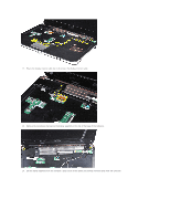
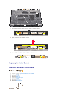
8. Remove the display assembly. 9. Remove the display bezel. 10. Remove the four screws that secure the display panel to the display assembly. 11. Disconnect the display camera cable.
-
 1
1 -
2
-
3
-
4
-
5
-
6
-
7
-
8
-
9
-
10
-
11
-
12
-
13
-
14
-
15
-
16
-
17
-
18
-
19
-
20
-
21
-
22
-
23
-
24
-
25
-
26
-
27
-
28
-
29
-
30
-
 31
31 -
 32
32 -
 33
33 -
 34
34 -
 35
35 -
 36
36 -
 37
37 -
 38
38 -
 39
39 -
 40
40 -
 41
41 -
42
-
43
-
44
-
45
-
46
-
47
-
48
-
49
-
50
-
51
-
52
-
53
-
54
-
55
-
56
-
57
-
58
-
59
-
60
-
61
-
62
-
63
-
64
-
65
-
66
-
67
-
68
-
69
-
70
-
71
-
72
-
73
-
74
-
75
-
76
 |
 |

8.
Remove the
display assembly
.
9.
Remove the
display bezel
.
10.
Remove the four screws that secure the display panel to the display assembly.
11.
Disconnect the display camera cable.