Dell XPS M1530 M1530 XPS M1530 Service Manual
Dell XPS M1530 M1530 Manual
 |
View all Dell XPS M1530 M1530 manuals
Add to My Manuals
Save this manual to your list of manuals |
Dell XPS M1530 M1530 manual content summary:
- Dell XPS M1530 M1530 | XPS M1530 Service Manual - Page 1
Dell™ XPS™ M1530 Service Manual Model PP28L www.dell.com | support.dell.com - Dell XPS M1530 M1530 | XPS M1530 Service Manual - Page 2
hardware or loss of data and tells you how to avoid the problem. CAUTION: A CAUTION indicates a potential for property damage, personal strictly forbidden. Trademarks used in this text: Dell, the DELL logo, and XPS are trademarks of Dell Inc.;Bluetooth is a registered trademark owned by Bluetooth - Dell XPS M1530 M1530 | XPS M1530 Service Manual - Page 3
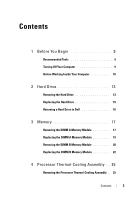
Contents 1 Before You Begin 9 Recommended Tools 9 Turning Off Your Computer 9 Before Working Inside Your Computer 10 2 Hard Drive 13 Removing the Hard Drive 13 Replacing the Hard Drive 15 Returning a Hard Drive to Dell 16 3 Memory 17 Removing the DIMM A Memory Module 17 Replacing the DIMM - Dell XPS M1530 M1530 | XPS M1530 Service Manual - Page 4
Replacing the Processor Thermal-Cooling Assembly . 28 5 Processor 31 Removing the Processor 31 Installing the Processor 32 6 Communication Cards 35 Subscriber Identity Module 35 Wireless Mini Cards 35 Removing a WLAN Card 36 Replacing a WLAN Card 38 Removing a Mobile Broadband or WWAN - Dell XPS M1530 M1530 | XPS M1530 Service Manual - Page 5
9 Battery Latch Assembly 51 Removing the Battery Latch Assembly 51 Replacing the Battery Latch Assembly 52 10 Keyboard 55 Removing the Keyboard 55 Replacing the Keyboard 56 11 Button Board 59 Removing the Button Board 59 Replacing the Button Board 60 12 Display Assembly 63 Removing the - Dell XPS M1530 M1530 | XPS M1530 Service Manual - Page 6
13 LCD Camera 73 Removing the LCD Camera 73 Replacing the LCD Camera 74 14 Palm Rest 75 Removing the Palm Rest 75 Replacing the Palm Rest 79 15 Biometric Module 81 Removing the Biometric Module 81 Replacing the Biometric Module 82 16 Optical Drive 83 Removing the Optical Drive 83 - Dell XPS M1530 M1530 | XPS M1530 Service Manual - Page 7
Replacing the Hard Drive Cage 90 19 ExpressCard Reader 93 Removing the ExpressCard Reader 93 Replacing the ExpressCard Reader 94 20 System Board 95 Removing the System Board 95 Replacing the System Board 96 21 S-Video Board 99 Removing the S-Video Board 99 Replacing the S-Video Board 100 - Dell XPS M1530 M1530 | XPS M1530 Service Manual - Page 8
24 Coin-Cell Battery 109 Removing the Coin-Cell Battery 109 Replacing the Coin-Cell Battery 110 25 Flashing the BIOS 113 Flashing the BIOS From a CD 113 Flashing the BIOS From the Hard Drive 113 26 Pin Assignments for I/O Connectors . . . 115 USB Connector 115 Video Connector 115 S-Video TV- - Dell XPS M1530 M1530 | XPS M1530 Service Manual - Page 9
on page 9 and "Before Working Inside Your Computer" on page 10. • You have read the safety information in the Dell™ Product Information Guide. • A component can be replaced or-if purchased separately-installed by performing the removal procedure in reverse order. Recommended Tools The procedures in - Dell XPS M1530 M1530 | XPS M1530 Service Manual - Page 10
begin any of the procedures in this section, follow the safety instructions in the Product Information Guide. NOTICE: Handle components and cards with care. Do not touch , you must remove the battery from the battery bay before you service the computer. NOTICE: To avoid damage to the computer, use - Dell XPS M1530 M1530 | XPS M1530 Service Manual - Page 11
7 Slide and click the battery latch release. 8 Slide the battery out of the battery bay. 1 2 1 battery 2 battery-bay latch release 9 Turn the computer top-side up, open the display, and press the power button to ground the system board. Before You Begin 11 - Dell XPS M1530 M1530 | XPS M1530 Service Manual - Page 12
12 Before You Begin - Dell XPS M1530 M1530 | XPS M1530 Service Manual - Page 13
section, follow the safety instructions in the Product Information Guide. NOTICE: To prevent Dell does not guarantee compatibility or provide support for hard drives from sources other than Reinstalling Drivers and Utilities" in your Owner's Manual). Removing the Hard Drive 1 Follow the procedures - Dell XPS M1530 M1530 | XPS M1530 Service Manual - Page 14
NOTICE: When the hard drive is not in the computer, store it in protective antistatic packaging (see "Protecting Against Electrostatic Discharge" in the Product Information Guide). 4 Remove the two screws from either side of the hard drive bezel and remove the bezel. 14 Hard Drive - Dell XPS M1530 M1530 | XPS M1530 Service Manual - Page 15
four screws on the hard drive cover. 5 Install the operating system for your computer, as needed (see "Restoring Your Operating System" in your computer Owner's Manual). 6 Install the drivers and utilities for your computer, as needed (see "Reinstalling Drivers and Utilities" in your computer Owner - Dell XPS M1530 M1530 | XPS M1530 Service Manual - Page 16
Returning a Hard Drive to Dell Return your old hard drive to Dell in its original, or comparable, foam packaging. Otherwise, the hard drive may be damaged in transit. 2 1 1 foam packaging 2 hard drive 16 Hard Drive - Dell XPS M1530 M1530 | XPS M1530 Service Manual - Page 17
in this section, follow the safety instructions in the Product Information Guide. You can increase your computer memory by installing memory modules on the system board. See "Specifications" in your Owner's Manual for information on the memory supported by your computer. Install only memory - Dell XPS M1530 M1530 | XPS M1530 Service Manual - Page 18
12 3 1 M2.5 x 5-mm screw 3 captive screw (4) 2 module cover 1 2 1 DIMM A memory module 2 DIMM B memory module NOTICE: To prevent damage to the memory module connector, do not use tools to spread the memory module securing clips. 18 Memory - Dell XPS M1530 M1530 | XPS M1530 Service Manual - Page 19
3 Use your fingertips to carefully spread apart the securing clips on each end of the memory module connector until the module pops up. 4 Remove the module from the connector. 1 2 3 1 upper memory module connector 3 memory module (DIMM A) 2 securing clip (2) Replacing the DIMM A Memory Module - Dell XPS M1530 M1530 | XPS M1530 Service Manual - Page 20
and automatically updates the system configuration information. To confirm the amount of memory installed in the computer, click Start → Help and Support→ Dell System Information. Removing the DIMM B Memory Module NOTICE: If a memory module is installed in the DIMM A connector, remove it prior - Dell XPS M1530 M1530 | XPS M1530 Service Manual - Page 21
12 3 1 M2.5 x 5-mm screw 3 captive screw (4) 2 module cover 1 2 1 DIMM A memory module 2 DIMM B memory module NOTICE: To prevent damage to the memory module connector, do not use tools to spread the memory module securing clips. Memory 21 - Dell XPS M1530 M1530 | XPS M1530 Service Manual - Page 22
NOTICE: To avoid electrostatic discharge, ground yourself by using a wrist grounding strap or by periodically touching an unpainted metal surface (such as a connector on the back of the computer). 3 Use your fingertips to carefully spread apart the securing clips on each end of the memory module - Dell XPS M1530 M1530 | XPS M1530 Service Manual - Page 23
detects the additional memory and automatically updates the system configuration information. To confirm the amount of memory installed in the computer, click Start → Help and Support→ Dell System Information. Memory 23 - Dell XPS M1530 M1530 | XPS M1530 Service Manual - Page 24
24 Memory - Dell XPS M1530 M1530 | XPS M1530 Service Manual - Page 25
4 Processor Thermal-Cooling Assembly CAUTION: Before working inside your computer, follow the safety instructions in the Product Information Guide. NOTICE: To avoid electrostatic discharge, ground yourself by using a wrist grounding strap or by periodically touching an unpainted metal surface (such - Dell XPS M1530 M1530 | XPS M1530 Service Manual - Page 26
12 3 1 M2.5 x 5-mm screw 3 captive screw (4) 2 module cover 3 Loosen the six captive screws along with the M2.5 x 5-mm screw from the thermal-cooling assembly. 26 Processor Thermal-Cooling Assembly - Dell XPS M1530 M1530 | XPS M1530 Service Manual - Page 27
1 2 3 1 thermal-cooling assembly 3 M2.5 x 5-mm screw 2 captive screw (6) Processor Thermal-Cooling Assembly 27 - Dell XPS M1530 M1530 | XPS M1530 Service Manual - Page 28
of the computer. Replacing the Processor Thermal-Cooling Assembly CAUTION: Before working inside your computer, follow the safety instructions in the Product Information Guide. NOTICE: To prevent static damage to components inside your computer, discharge static electricity from your body before - Dell XPS M1530 M1530 | XPS M1530 Service Manual - Page 29
NOTE: This procedure assumes that you have already removed the processor thermal-cooling assembly and are ready to replace it. 1 Peel the backing off the thermal cooling pad and adhere the pad to the portion of the thermal-cooling assembly that covers the processor. 2 Place the assembly on the - Dell XPS M1530 M1530 | XPS M1530 Service Manual - Page 30
30 Processor Thermal-Cooling Assembly - Dell XPS M1530 M1530 | XPS M1530 Service Manual - Page 31
5 Processor CAUTION: Before working inside your computer, follow the safety instructions in the Product Information Guide. NOTICE: To avoid electrostatic discharge, ground yourself by using a wrist grounding strap or by periodically touching an unpainted metal surface (such as a connector on the - Dell XPS M1530 M1530 | XPS M1530 Service Manual - Page 32
1 23 4 1 processor 2 pin-1 corner of processor 4 ZIF-socket cam screw 3 ZIF socket 4 Use a processor extraction tool to remove the processor. Installing the Processor NOTICE: Ensure that the cam lock is in the fully open position before seating the processor. Seating the processor properly in - Dell XPS M1530 M1530 | XPS M1530 Service Manual - Page 33
When the processor is correctly seated, all four corners are aligned at the same height. If one or more corners of the processor are higher than the others, the processor is not seated correctly. NOTICE: To prevent intermittent contact between the ZIF-socket cam screw and the processor when removing - Dell XPS M1530 M1530 | XPS M1530 Service Manual - Page 34
34 Processor - Dell XPS M1530 M1530 | XPS M1530 Service Manual - Page 35
2 1 SIM 2 battery bay Wireless Mini Cards CAUTION: Before you begin any of the procedures in this section, follow the safety instructions in the Product Information Guide. NOTICE: To help prevent damage to the system board, you must remove the battery from the battery bay before you begin working - Dell XPS M1530 M1530 | XPS M1530 Service Manual - Page 36
If you ordered a wireless Mini Card with your computer, the card is already installed. Your computer supports three types of wireless Mini Cards: • Wireless Local Area Network (WLAN) • Ultra Wide Band (UWB) • Mobile Broadband or Wireless Wide Area Network (WWAN) Removing a WLAN - Dell XPS M1530 M1530 | XPS M1530 Service Manual - Page 37
1 2 3 1 WLAN card 2 M2 x 3-mm securing screw 3 antenna cable connectors (2) 5 Release the WLAN card by removing the securing screw. 6 Lift the WLAN card out of its system board connector. Communication Cards 37 - Dell XPS M1530 M1530 | XPS M1530 Service Manual - Page 38
Replacing a WLAN Card NOTICE: The connectors are keyed to ensure correct insertion. If you feel resistance, check the connectors on the card and on the system board, and realign the card. NOTICE: To avoid damage to the WLAN card, never place cables under the card. 1 Insert the WLAN card connector at - Dell XPS M1530 M1530 | XPS M1530 Service Manual - Page 39
the captive screws. Removing a Mobile Broadband or WWAN Card NOTE: WWAN is also available on an ExpressCard (see "Using ExpressCards" in your Owner's Manual). 1 Follow the procedures in "Before You Begin" on page 9. 2 Turn the computer over. 3 Loosen the two captive screws on the Mini Card module - Dell XPS M1530 M1530 | XPS M1530 Service Manual - Page 40
4 Disconnect the two antenna cables from the WWAN card. 1 2 3 1 WWAN card 2 M2 x 3-mm securing screw 3 antenna cable connectors (2) 5 Release the WWAN card by removing the securing screw. 6 Lift the WWAN card out of its system board connector. 40 Communication Cards - Dell XPS M1530 M1530 | XPS M1530 Service Manual - Page 41
Replacing a WWAN Card NOTICE: The connectors are keyed to ensure correct insertion. If you feel resistance, check the connectors on the card and on the system board, and realign the card. NOTICE: To avoid damage to the WWAN card, never place cables under the card. 1 Insert the WWAN card connector at - Dell XPS M1530 M1530 | XPS M1530 Service Manual - Page 42
Flash Cache Module or Ultra Wide Band If you ordered an FCM card or an UWB card with your computer, it is already installed. Only one of the cards can be installed in the slot provided. The Flash Cache Module (FCM) is an internal memory card that helps improve the performance of your computer. The - Dell XPS M1530 M1530 | XPS M1530 Service Manual - Page 43
4 Ground yourself by touching one of the metal connectors on the back of the computer. NOTE: If you leave the area, ground yourself again when you return to the computer. 5 Remove the M2 x 3-mm securing screw. NOTE: In case of an UWB card, disconnect the blue antenna cable from the UWB card. 6 - Dell XPS M1530 M1530 | XPS M1530 Service Manual - Page 44
4 Secure unused antenna cables in the protective mylar sleeve. 5 Replace the cover and tighten the captive screws. 44 Communication Cards - Dell XPS M1530 M1530 | XPS M1530 Service Manual - Page 45
Covers and Center Control Cover CAUTION: Before you begin any of the procedures in this section, follow the safety instructions in the Product Information Guide. NOTICE: To avoid electrostatic discharge, ground yourself by using a wrist grounding strap or by periodically touching an unpainted metal - Dell XPS M1530 M1530 | XPS M1530 Service Manual - Page 46
1 2 3 4 1 center control cover 4 black securing tabs 2 center control cover cable connector 3 center control cover cable 5 Pull the black securing tabs of the cable connector with your fingertips and ease out the cable. 6 Remove the hinge covers from each side of the computer. 46 Hinge - Dell XPS M1530 M1530 | XPS M1530 Service Manual - Page 47
1 2 1 center control cover 2 hinge cover (2) Replacing the Hinge Covers and Center Control Cover 1 Replace the hinge covers. 2 To reconnect the cable that attaches the center control cover to the system board, place the cable inside the cable connector and push its black securing tabs inside with - Dell XPS M1530 M1530 | XPS M1530 Service Manual - Page 48
48 Hinge Covers and Center Control Cover - Dell XPS M1530 M1530 | XPS M1530 Service Manual - Page 49
With Bluetooth® Wireless Technology CAUTION: Before you begin any of the procedures in this section, follow the safety instructions in the Product Information Guide. NOTICE: To avoid electrostatic discharge, ground yourself by using a wrist grounding strap or by periodically touching an unpainted - Dell XPS M1530 M1530 | XPS M1530 Service Manual - Page 50
1 2 3 1 box 2 bluetooth card 3 cable connector 5 Disconnect the cable connector from the card. 6 Remove the card from the computer. Replacing the Card 1 Connect the cable connector to the card. 2 Insert the bluetooth card into the box. 3 Replace the center control cover (see "Replacing the Hinge - Dell XPS M1530 M1530 | XPS M1530 Service Manual - Page 51
9 Battery Latch Assembly CAUTION: Before you begin the following procedure, follow the safety instructions in the Product Information Guide. NOTICE: To avoid electrostatic discharge, ground yourself by using a wrist grounding strap or by periodically touching an unpainted metal surface (such as the - Dell XPS M1530 M1530 | XPS M1530 Service Manual - Page 52
1 2 3 1 spring 3 plastic clips 2 battery latch assembly 8 Remove the spring from the hook on the computer base by lifting it up and away with a screwdriver or a plastic scribe. 9 Remove the plastic battery-latch assembly starting from the right side corner and proceeding towards the other end as - Dell XPS M1530 M1530 | XPS M1530 Service Manual - Page 53
4 Replace the system board (see "Replacing the System Board" on page 96). 5 Replace in reverse order the other components that you removed in "Removing the Battery Latch Assembly" on page 51. Battery Latch Assembly 53 - Dell XPS M1530 M1530 | XPS M1530 Service Manual - Page 54
54 Battery Latch Assembly - Dell XPS M1530 M1530 | XPS M1530 Service Manual - Page 55
about the keyboard, see "Using the Keyboard and Touchpad" in your Owner's Manual. CAUTION: Before you begin any of the procedures in this section, follow the safety instructions in the Product Information Guide. NOTICE: To avoid electrostatic discharge, ground yourself by using a wrist grounding - Dell XPS M1530 M1530 | XPS M1530 Service Manual - Page 56
1 2 3 4 5 1 M2.5 x 5-mm screw (2) 3 keyboard tab (5) 5 plastic securing bar 2 keyboard 4 keyboard cable 5 Pull up on the plastic bar that secures the keyboard cable to the system board and remove the keyboard Replacing the Keyboard 1 Slide the keyboard cable connector into the slot until it - Dell XPS M1530 M1530 | XPS M1530 Service Manual - Page 57
4 Replace the Hinge Covers and the Center Control Cover (see "Replacing the Hinge Covers and Center Control Cover" on page 47). Keyboard 57 - Dell XPS M1530 M1530 | XPS M1530 Service Manual - Page 58
58 Keyboard - Dell XPS M1530 M1530 | XPS M1530 Service Manual - Page 59
11 Button Board CAUTION: Before you begin any of the procedures in this section, follow the safety instructions in the Product Information Guide. NOTICE: To avoid electrostatic discharge, ground yourself by using a wrist grounding strap or by periodically touching an unpainted metal surface (such as - Dell XPS M1530 M1530 | XPS M1530 Service Manual - Page 60
21 3 4 1 screw (2) 3 button board cable 2 button board 4 black securing tabs 4 Remove the two screws securing the button board. 5 To release the button board cable, pull the black securing tabs of the cable connector with your fingertips and ease out the cable. 6 Remove the button board from - Dell XPS M1530 M1530 | XPS M1530 Service Manual - Page 61
3 Replace the two screws that secure the button board to the system board. 4 Replace the keyboard (see "Replacing the Keyboard" on page 56). 5 Replace the Hinge Covers and the Center Control Cover (see "Replacing the Hinge Covers and Center Control Cover" on page 47). Button Board 61 - Dell XPS M1530 M1530 | XPS M1530 Service Manual - Page 62
62 Button Board - Dell XPS M1530 M1530 | XPS M1530 Service Manual - Page 63
12 Display Assembly CAUTION: Before you begin any of the procedures in this section, follow the safety instructions in the Product Information Guide. NOTICE: To avoid electrostatic discharge, ground yourself by using a wrist grounding strap or by periodically touching an unpainted metal surface ( - Dell XPS M1530 M1530 | XPS M1530 Service Manual - Page 64
applicable (see "Wireless Mini Cards" on page 35). 5 Make note of the cable routing and carefully dislodge the Mini-Card antenna cables from their routing guides. 64 Display Assembly - Dell XPS M1530 M1530 | XPS M1530 Service Manual - Page 65
6 Remove the two M2.5 x 5-mm screws labeled "D" from the computer base. 7 Remove the keyboard (see "Removing the Keyboard" on page 55). 8 Remove the two M2.5 x 8-mm screws from each side of the display assembly. Display Assembly 65 - Dell XPS M1530 M1530 | XPS M1530 Service Manual - Page 66
9 Make note of the cable routing and carefully dislodge the Mini-Card antenna cables from their routing guides and pull the cables with their connectors through the system board so that they are clear of the computer base. 10 Pull on the display - Dell XPS M1530 M1530 | XPS M1530 Service Manual - Page 67
the system board. 3 Make note of the cable routing and carefully slide the Mini-Card antenna cables through the system board and into their routing guides. 4 Replace the two M2.5 x 8-mm screws on each side of the display assembly. 5 Replace the keyboard (see "Replacing the Keyboard" on page 56 - Dell XPS M1530 M1530 | XPS M1530 Service Manual - Page 68
mm screws labeled "D" on the computer base. 7 Make note of the cable routing and carefully insert the Mini-Card antenna cables through their routing guides. 8 Reconnect the mini card cables to the Mini Cards if applicable (see "Wireless Mini Cards" on page 35). 9 Replace the hinge covers and center - Dell XPS M1530 M1530 | XPS M1530 Service Manual - Page 69
1 display bezel Replacing the Display Bezel Realign the display bezel over the display panel, and gently snap into place. Removing the Display Panel 1 Remove the display assembly (see "Removing the Display Assembly" on page 63). 2 Remove the display bezel (see "Removing the Display Bezel" on page 68 - Dell XPS M1530 M1530 | XPS M1530 Service Manual - Page 70
5 Remove the eight screws (four on each side) that secure the display panel brackets to the display panel. 1 2 1 display panel bracket (1 left, 1 right) 2 screw (8 total; 4 on each side) Replacing the Display Panel 1 Attach the display bracket to the display panel by replacing the four screws on - Dell XPS M1530 M1530 | XPS M1530 Service Manual - Page 71
Turn over the display panel, placing it on a clean surface. NOTICE: To avoid damage to the computer when replacing the bottom flex cable, gently support the bottom of the inverter board with one finger as you reseat the bottom flex-cable connector. Do not bend the inverter board. 4 1 3 2 1 pull - Dell XPS M1530 M1530 | XPS M1530 Service Manual - Page 72
72 Display Assembly - Dell XPS M1530 M1530 | XPS M1530 Service Manual - Page 73
13 LCD Camera CAUTION: Before working inside your computer, follow the safety instructions in the Product Information Guide. NOTICE: To avoid electrostatic discharge, ground yourself by using a wrist grounding strap or by periodically touching an unpainted metal surface (such as a connector on the - Dell XPS M1530 M1530 | XPS M1530 Service Manual - Page 74
7 Disconnect the camera cable from the connector. 8 Remove the LCD camera. Replacing the LCD Camera 1 Align the camera over the screw holes. 2 Replace the two screws that secure the camera to the display. 3 Reconnect the camera cable to the connector. 4 Replace the display panel (see "Replacing the - Dell XPS M1530 M1530 | XPS M1530 Service Manual - Page 75
14 Palm Rest CAUTION: Before you begin any of the procedures in this section, follow the safety instructions in the Product Information Guide. NOTICE: To avoid electrostatic discharge, ground yourself by using a wrist grounding strap or by periodically touching an unpainted metal surface (such as - Dell XPS M1530 M1530 | XPS M1530 Service Manual - Page 76
9 Turn the computer top side up and remove the single screw from the top of the palm rest. 76 Palm Rest - Dell XPS M1530 M1530 | XPS M1530 Service Manual - Page 77
1 2 3 4 5 1 screw 3 touch pad cable connector 5 biometric cable connector 2 bluetooth cable connector 4 palm rest NOTICE: Pull on the plastic tab on top of the connectors to avoid damaging the connectors. 10 Disconnect the bluetooth cable connector, touch pad cable connector and the biometric - Dell XPS M1530 M1530 | XPS M1530 Service Manual - Page 78
1 2 1 palm rest 2 suspend switch cable connector 13 Disconnect the suspend switch cable to separate the palm rest from the computer base. NOTICE: Carefully separate the palm rest from the computer base to avoid damage to the palm rest. 78 Palm Rest - Dell XPS M1530 M1530 | XPS M1530 Service Manual - Page 79
Replacing the Palm Rest 1 Align the palm rest with the computer base and connect the suspend switch cable. 2 Gently snap the palm rest into place. 3 Connect the bluetooth cable, touch pad cable and the biometric cable to the system board. 4 Replace the screw on the top of the palm rest. 5 Turn the - Dell XPS M1530 M1530 | XPS M1530 Service Manual - Page 80
80 Palm Rest - Dell XPS M1530 M1530 | XPS M1530 Service Manual - Page 81
15 Biometric Module CAUTION: Before you begin any of the procedures in this section, follow the safety instructions in the Product Information Guide. NOTICE: To avoid electrostatic discharge, ground yourself by using a wrist grounding strap or by periodically touching an unpainted metal surface ( - Dell XPS M1530 M1530 | XPS M1530 Service Manual - Page 82
1 2 3 1 screw (2) 2 3 palm rest (view from below) biometric module 7 Remove the biometric module. Replacing the Biometric Module 1 Replace the biometric module. 2 Replace the two screws that secure the biometric module to the computer base. 3 Replace the palm rest (see "Replacing the Palm - Dell XPS M1530 M1530 | XPS M1530 Service Manual - Page 83
16 Optical Drive CAUTION: Before you begin any of the procedures in this section, follow the safety instructions in the Product Information Guide. NOTICE: To avoid electrostatic discharge, ground yourself by using a wrist grounding strap or by periodically touching an unpainted metal surface (such - Dell XPS M1530 M1530 | XPS M1530 Service Manual - Page 84
1 2 3 1 optical drive 3 cable connector 2 M2 x 3-mm screw (2) 7 Slide the drive at an angle toward the side of the computer. 8 Remove the cable connector from the back of the drive. 9 Lift the drive out of the computer base. Replacing the Optical Drive 1 Connect the cable connector to the back - Dell XPS M1530 M1530 | XPS M1530 Service Manual - Page 85
17 Speaker CAUTION: Before you begin any of the procedures in this section, follow the safety instructions in the Product Information Guide. NOTICE: To avoid electrostatic discharge, ground yourself by using a wrist grounding strap or by periodically touching an unpainted metal surface (such as the - Dell XPS M1530 M1530 | XPS M1530 Service Manual - Page 86
2 3 1 1 speaker cable connector 2 screw (2) 3 speaker cable routing 11 Disconnect the speaker cable connector from the system board. 12 Make note of the speaker cable routing. 13 Remove the speakers. Replacing the Speaker 1 Replace the speakers and the speaker cables. 2 Connect the speaker - Dell XPS M1530 M1530 | XPS M1530 Service Manual - Page 87
7 Replace the keyboard (see "Replacing the Keyboard" on page 56). 8 Replace the hinge covers and center control cover (see "Replacing the Hinge Covers and Center Control Cover" on page 47). 9 Replace the hard drive (see "Replacing the Hard Drive" on page 15). 10 Reinstall the memory modules or Mini - Dell XPS M1530 M1530 | XPS M1530 Service Manual - Page 88
88 Speaker - Dell XPS M1530 M1530 | XPS M1530 Service Manual - Page 89
18 Hard Drive Cage CAUTION: Before you begin any of the procedures in this section, follow the safety instructions in the Product Information Guide. NOTICE: To avoid electrostatic discharge, ground yourself by using a wrist grounding strap or by periodically touching an unpainted metal surface (such - Dell XPS M1530 M1530 | XPS M1530 Service Manual - Page 90
1 2 1 screw 2 hard drive cage 8 Push the hard drive cage to the side to release it from the pin holding the cage in place. 9 Slide the hard drive cage forward at an angle and lift it out. Replacing the Hard Drive Cage 1 Replace the hard drive cage. 2 Replace the screw that secures the hard - Dell XPS M1530 M1530 | XPS M1530 Service Manual - Page 91
6 Replace the hinge covers and center control cover (see "Replacing the Hinge Covers and Center Control Cover" on page 47). 7 Replace the hard drive (see "Replacing the Hard Drive" on page 15). Hard Drive Cage 91 - Dell XPS M1530 M1530 | XPS M1530 Service Manual - Page 92
92 Hard Drive Cage - Dell XPS M1530 M1530 | XPS M1530 Service Manual - Page 93
19 ExpressCard Reader CAUTION: Before performing the following procedures, follow the safety instructions in the Product Information Guide. NOTICE: To avoid electrostatic discharge, ground yourself by using a wrist grounding strap or by periodically touching a connector on the back panel of the - Dell XPS M1530 M1530 | XPS M1530 Service Manual - Page 94
1 2 1 M2 x 3-mm screws (3) 2 ExpressCard reader 6 Pull up on the ExpressCard reader to disconnect it from the system board. Replacing the ExpressCard Reader 1 Replace the ExpressCard reader. 2 Replace the three M2 x 3-mm screws that secure the ExpressCard reader to the computer base. 3 Replace - Dell XPS M1530 M1530 | XPS M1530 Service Manual - Page 95
procedures in this section, follow the safety instructions in the Product Information Guide. NOTICE: To avoid electrostatic discharge, ground system board includes a CD that provides a utility for transferring the Service Tag to the replacement system board. NOTICE: Handle components and cards - Dell XPS M1530 M1530 | XPS M1530 Service Manual - Page 96
11 Disconnect the button board cable from the system board connector (see "Removing the Button Board" on page 59). 12 Disconnect the speaker cable from the system board (see "Removing the Speaker" on page 85). 13 Remove the three remaining M2.5 x 5-mm screws that secure the system board to the - Dell XPS M1530 M1530 | XPS M1530 Service Manual - Page 97
NOTE: After you have replaced the system board, enter the computer Service Tag into the BIOS of the replacement system board. 3 Insert the CD that accompanied the replacement system board into the appropriate drive. Follow the instructions that appear on the screen. System Board 97 - Dell XPS M1530 M1530 | XPS M1530 Service Manual - Page 98
98 System Board - Dell XPS M1530 M1530 | XPS M1530 Service Manual - Page 99
21 S-Video Board CAUTION: Before you begin any of the procedures in this section, follow the safety instructions in the Product Information Guide. NOTICE: To avoid electrostatic discharge, ground yourself by using a wrist grounding strap or by periodically touching an unpainted metal surface (such - Dell XPS M1530 M1530 | XPS M1530 Service Manual - Page 100
1 2 3 4 5 6 1 system board 3 S-Video board 5 S-Video connector 2 screw 4 USB connector SIM card slot 4 Detach the S-Video board from the system board connector. Replacing the S-Video Board 1 Attach the S-Video board to the system board connector. 2 Replace the screw that secures the S-Video - Dell XPS M1530 M1530 | XPS M1530 Service Manual - Page 101
6 Replace the optical drive (see "Replacing the Optical Drive" on page 84). 7 Replace the palm rest (see "Replacing the Palm Rest" on page 79). 8 Replace the keyboard (see "Replacing the Keyboard" on page 56). 9 Replace the hinge covers and center control cover (see "Replacing the Hinge Covers and - Dell XPS M1530 M1530 | XPS M1530 Service Manual - Page 102
102 S-Video Board - Dell XPS M1530 M1530 | XPS M1530 Service Manual - Page 103
22 Wireless Sniffer Board CAUTION: Before you begin any of the procedures in this section, follow the safety instructions in the Product Information Guide. NOTICE: To avoid electrostatic discharge, ground yourself by using a wrist grounding strap or by periodically touching an unpainted metal - Dell XPS M1530 M1530 | XPS M1530 Service Manual - Page 104
1 2 3 1 wireless sniffer board 2 M2 x3-mm screw (2) 3 wireless sniffer board cable connector Replacing the Wireless Sniffer Board 1 Replace the sniffer board. 2 Replace the two M2 x 3-mm screws on each side of the sniffer board. 3 Reconnect the wireless sniffer board cable to the system board. 4 - Dell XPS M1530 M1530 | XPS M1530 Service Manual - Page 105
23 Charger Board CAUTION: Before you begin any of the procedures in this section, follow the safety instructions in the Product Information Guide. NOTICE: To avoid electrostatic discharge, ground yourself by using a wrist grounding strap or by periodically touching an unpainted metal surface (such - Dell XPS M1530 M1530 | XPS M1530 Service Manual - Page 106
1 2 3 4 5 6 7 8 9 1 screw (2) 3 USB connector (2) 5 VGA connector 7 system board 9 IEEE 1394a connector 2 AC adapter connector 4 charger board 6 network connector (RJ-45) 8 HDMI connector 4 Turn the system board over and detach the charger board from the system board connector. 106 Charger - Dell XPS M1530 M1530 | XPS M1530 Service Manual - Page 107
1 2 3 1 charger board (view from below) 3 system board (view from below) 2 system board connector Replacing the Charger Board 1 Attach the charger board to the system board connector. 2 Replace the two screws that secure the charger board to the system board connector. 3 Replace the system board - Dell XPS M1530 M1530 | XPS M1530 Service Manual - Page 108
9 Replace the hinge covers and center control cover (see "Replacing the Hinge Covers and Center Control Cover" on page 47). 108 Charger Board - Dell XPS M1530 M1530 | XPS M1530 Service Manual - Page 109
24 Coin-Cell Battery CAUTION: Before you begin any of the procedures in this section, follow the safety instructions in the Product Information Guide. NOTICE: To avoid electrostatic discharge, ground yourself by using a wrist grounding strap or by periodically touching an unpainted metal surface ( - Dell XPS M1530 M1530 | XPS M1530 Service Manual - Page 110
1 2 1 coin-cell battery 2 S-Video board 5 Use a screw driver to push the coin cell battery forward and upward to release it from the slot. Replacing the Coin-Cell Battery 1 Replace the coin cell battery. 2 Replace the S-Video board (see "Replacing the S-Video Board" on page 100). 3 Replace the - Dell XPS M1530 M1530 | XPS M1530 Service Manual - Page 111
7 Replace the palm rest (see "Replacing the Palm Rest" on page 79). 8 Replace the keyboard (see "Replacing the Keyboard" on page 56). 9 Replace the center control cover (see "Replacing the Hinge Covers and Center Control Cover" on page 47). Coin-Cell Battery 111 - Dell XPS M1530 M1530 | XPS M1530 Service Manual - Page 112
112 Coin-Cell Battery - Dell XPS M1530 M1530 | XPS M1530 Service Manual - Page 113
Insert the BIOS-update program CD, and restart the computer. Follow the instructions that appear on the screen. The computer continues to boot and updates the the computer. 3 Locate the latest BIOS update file for your computer at support.dell.com. 4 Click Download Now to download the file. 5 If the - Dell XPS M1530 M1530 | XPS M1530 Service Manual - Page 114
on your desktop and is titled the same as the downloaded BIOS update file. 9 Double-click the file icon on the desktop and follow the instructions on the screen. 114 Flashing the BIOS - Dell XPS M1530 M1530 | XPS M1530 Service Manual - Page 115
26 Pin Assignments for I/O Connectors USB Connector Pin Signal 1 USB5V+ 2 USBP- 3 USBP+ 4 GND Video Connector NOTE: The color of the video connector may vary in color between blue and black. Pin Assignments for I/O Connectors 115 - Dell XPS M1530 M1530 | XPS M1530 Service Manual - Page 116
Pin Signal 1 CRT_R 2 CRT_G 3 CRT_B 4 NC 5 GND 6 GND 7 GND 8 GND Pin Signal 9 5V+ 10 GND 11 MONITOR_DETECT- 12 DDC_DATA 13 CRT_HS 14 CRT_VS 15 DDC_CLK S-Video TV-Out Connector 116 Pin Assignments for I/O Connectors - Dell XPS M1530 M1530 | XPS M1530 Service Manual - Page 117
S-Video Pin Signal 1 GND 2 GND 3 DLUMA-L 4 DCRMA-L Composite Video Pin Signal 5 GND 6 DCMPS-L 7 NC HDMI Connector 19 17 15 13 11 9 7 5 3 1 20 18 16 14 12 10 8 6 4 Pin Assignments for I/O Connectors 117 - Dell XPS M1530 M1530 | XPS M1530 Service Manual - Page 118
Pin Signal 1 TMDS Data 2+ 2 TMDS Data 2 Shield 3 TMDS Data 24 TMDS Data 1+ 5 TMDS Data 1 Shield 6 TMDS Data 17 TMDS Data 0+ 8 TMDS Data 0 Shield 9 TMDS Data 010 TMDS Clock+ IEEE 1394a Connector Pin Signal 11 TMDS Clock Shield 12 TMDS Clock- 13 CEC 14 No Connect 15 DDC Clock 16 DDC Data 17 Ground 18
-
 1
1 -
 2
2 -
 3
3 -
 4
4 -
 5
5 -
 6
6 -
 7
7 -
8
-
9
-
10
-
11
-
12
-
13
-
14
-
15
-
16
-
17
-
18
-
19
-
20
-
21
-
22
-
23
-
24
-
25
-
26
-
27
-
28
-
29
-
30
-
31
-
32
-
33
-
34
-
35
-
36
-
37
-
38
-
39
-
40
-
41
-
42
-
43
-
44
-
45
-
46
-
47
-
48
-
49
-
50
-
51
-
52
-
53
-
54
-
55
-
56
-
57
-
58
-
59
-
60
-
61
-
62
-
63
-
64
-
65
-
66
-
67
-
68
-
69
-
70
-
71
-
72
-
73
-
74
-
75
-
76
-
77
-
78
-
79
-
80
-
81
-
82
-
83
-
84
-
85
-
86
-
87
-
88
-
89
-
90
-
91
-
92
-
93
-
94
-
95
-
96
-
97
-
98
-
99
-
100
-
101
-
102
-
103
-
104
-
105
-
106
-
107
-
108
-
109
-
110
-
111
-
112
-
113
-
114
-
115
-
116
-
117
-
118
 |
 |

www.dell.com | support.dell.com
Dell™ XPS™ M1530 Service Manual
Model PP28L