Denon DCM-65 Owners Manual - Page 9
CONNECTIONS, NORMAL PLAY, Connecting the Digital Output Jack COAXIAL DCM-65 only
 |
View all Denon DCM-65 manuals
Add to My Manuals
Save this manual to your list of manuals |
Page 9 highlights
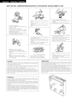
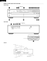
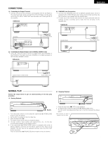
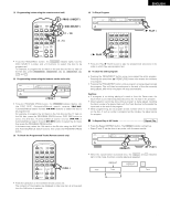
ENGLISH CONNECTIONS (1) Connecting the Output Terminal • Connect one end of the connection cord supplied with the CD Player to the output terminals, left (L) and right (R) of the CD Player, and the other end to the CD, AUX or TAPE PLAY input terminals, left (L) and right (R), of the amplifier. DCM-65/35 LINE OUT VARIABLE IN OUT SYNCHRO CONTROL COAXIAL DIGITAL OUT (3) SYNCHRO Jack Connections • Connect the SYNCHRO jack with a DENON cassette deck which is equipped with a SYNCHRO jack, then make a synchronized recording. Use the connection cord supplied with the cassette deck. • To make use of this function, also connect the output jacks and make the settings so that a recording can be made from the CD player to the cassette deck. DCM-65/35 LINE OUT VARIABLE IN OUT SYNCHRO CONTROL COAXIAL DIGITAL OUT (Amplifier) SIGNAL GND INPUTS PHONO CD TUNER AUX L PB REC TAPE-1 TAPE-2 TAPE-1 TAPE-2 /DAT /MD /DAT /MD L R R SPEAKER SYSTEMS R L A B Power supply outlet AC OUTLET (Cassette Deck) Power supply outlet (2) Connecting the Digital Output Jack (COAXIAL) (DCM-65 only) • Use a 75 Ω/ohm pin cord to connect the digital output jack (COAXIAL) of the DCM-65 to the digital input jack (COAXIAL) on a digital processor or MD recorder, available in stores. DCM-65/35 LINE OUT VARIABLE IN OUT SYNCHRO CONTROL COAXIAL DIGITAL OUT Digital processor or MD recorder DIGITAL INPUT COAXIAL OPTICAL Power supply outlet NORMAL PLAY Follow the steps below to get an understanding of the disc play procedure. (1) Starting Playback PCM AUDIO TECHNOLOGY / CD AUTO CHANGER DCM-65 ¢ ON £ OFF PHONES HDCD REMOTE SENSOR 1 2 TRACK ¤ ,⁄ 3 DISC 4 5 MIN SEC 1234 5678 9 101112 13141516 5 DISC AUTOMATIC DISC LOADING SYSTEM REPEAT PROG STOP PAUSE PLAY OPEN/CLOSE DISC SKIP ( 1 PLAY ) 1. Turn the power switch on and press the open/close (5 OPEN/CLOSE) button to open the drawer. 2. Set the disc to be played in the front side tray. 3. Press the play button (1). 4. The drawer closes and the disc just loaded is played. 5. The disc number, track number and elapsed time, etc., for the disc currently playing appear on the display window. 6. If the open/close (5 OPEN/CLOSE) button is pressed while a disc is playing, playback continues, but the drawer opens and four discs can be replaced. The disc that can be replaced switches when the DISC SKIP button is pressed. Press the open/close (5 OPEN/CLOSE) button again to close the drawer. (2) Stopping Playback PCM AUDIO TECHNOLOGY / CD AUTO CHANGER DCM-65 ¢ ON £ OFF PHONES HDCD REMOTE SENSOR 1 2 TRACK ¤ ,⁄ 3 DISC 4 5 MIN SEC 1234 5678 9 101112 13141516 5 DISC AUTOMATIC DISC LOADING SYSTEM REPEAT PROG STOP PAUSE PLAY OPEN/CLOSE DISC SKIP ( 2 STOP ) 1. Press the stop button (2 STOP) to stop playback. 2. To replace discs, press the open/close (5 OPEN/CLOSE) button. The disc which was playing switches over to the front side and the drawer opens. • Set the disc you want to played in the front side. PCM AUDIO TECHNOLOGY / CD AUTO CHANGER DCM-65 HDCD REMOTE SENSOR 1 2 TRACK ¤ ,⁄ 3 DISC 4 5 MIN SEC 1234 5678 9 101112 13141516 ¢ ON £ OFF PHONES REPEAT PROG STOP PAUSE PLAY OPEN/CLOSE DISC SKIP 5 DISC AUTOMATIC DISC LOADING SYSTEM 9
-
 1
1 -
2
-
3
-
 4
4 -
 5
5 -
 6
6 -
 7
7 -
 8
8 -
 9
9 -
 10
10 -
 11
11 -
 12
12 -
 13
13 -
 14
14 -
15
-
16
-
17
-
18
-
19
-
20
-
21
-
22
-
23
-
24
-
25
-
26
-
27
-
28
-
29
-
30
-
31
-
32
-
33
-
34
-
35
-
36
-
37
-
38
 |
 |
