Denon DN X100 Operating Instructions - Page 6
English - mixer crossfader
 |
UPC - 081757506335
View all Denon DN X100 manuals
Add to My Manuals
Save this manual to your list of manuals |
Page 6 highlights
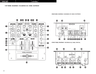
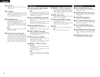
ENGLISH !4 Crossfader • Fades the overall mixer output between channels 1 and 2. !5 Level Meter • The dual LED's indicators are used to detail either the master output level, a combination of the master output level and the CUE signal level, or the PGM1/2 monaural level. !6 CH REVERSE button • This switch allows the left hand fader or right hand fader to control PGM1 or PGM2. • When the CH REVERSE mode is ON, the CH1 fader will be able to control PGM 2 sound and the CH2 fader will be able to control PGM 1 sound.. NOTE: • Please don't confuse with the CH 1/2 FADER REVERSE switch (#2). !7 Level meter mode select switch • The position of this switch will determine the Level Meter mode. In the "MASTER" position, the meter will detail the out level of the left and right channels. In the "PGM 1/2" position, the left side of the meter will indicate monaural level of the PGM 1 and the right side of the meter will indicate monaural level of the PGM 2. (2) Rear panel !8 Power operation switch (POWER) • Selects power "ON" or "OFF". NOTE: Whenever the power switch is in the OFF state, the AC adaptor is still connected on AC line voltage. Please be sure to unplug the cord when you don't use for along time. !9 Balanced MASTER OUT jacks (BAL.) • These 1/4" TRS jacks provide a balanced line level output. • Connect these jacks to the balanced analog input jacks on an amplifier or console. • Pin layout: Tip=Hot Ring=Cold Sleeve=GND @0 MIC BALANCED INPUT jack • Accepts an balanced microphone with 1/4" TRS mono jacks. • Pin layout: Tip=Hot Ring=Cold Sleeve=GND @1 PGM1, 2 FADER output jacks • Connect these jacks to the FADER input jacks of DN-S3000, DN-S5000, DN-S1000 and etc. using the 3.5mm stereo mini cord. @2 Phono ground screw (GND) • This screws provide a place to connect the ground wire from a turntable. • This terminal is exclusively for a turntable ground and not a safety earth ground. @3 PHONO1, 2 / LINE1, 3 switches (LN / PH) • These switches change the input from PHONO to a LINE level input. • These switches set a LINE level input when turntable is not connected. NOTE: Always be sure main power is shut off before change the position of the Line Level Selector Switch. @4 PHONO1, 2 / LINE1, 3 input jacks • These stereo pair of unbalanced RCA jacks are inputs for a PHONO (RIAA) stage for magnetic (MM) cartridges or a LINE stage suitable for any device, such as a CD player. @5 LINE2, 4 input jacks • These stereo pair of unbalanced RCA jacks are inputs for any line level device. @6 Unbalanced MASTER OUT jacks • This stereo pair of RCA jacks provides an unbalanced line level output. • Connect these jacks to the unbalanced analog input jacks on an amplifier or console. @7 AC IN • Input connection for the included AC adaptor. NOTE: Use specified attached AC adaptor only. (3) Front panel @8 CH 1/2 FADER START switches • Use this to switch the Channel Fader Start function ON and OFF. @9 CROSSFADER START A/B switches • Use this to switch the Crossader Start function ON and OFF. #0 HEADPHONE output jack • Accept 1/4" stereo headphone plugs. #1 CH 1/2 FADER CONTOUR adjustment • Adjusts the curve of the CH1/2 faders between fast, normal , or slow fade. #2 CH 1/2 FADER REVERSE switch • Reverses the direction of each respective input CH1/2 fader. #3 CROSSFADER CONTOUR adjustment • Adjusts the shape of the crossfader curve from a fast cut for scratching or to a slow fade for mixing. #4 CROSSFADER REVERSE switch • Reverses the direction of the crossfader. 6
-
 1
1 -
 2
2 -
 3
3 -
 4
4 -
 5
5 -
 6
6 -
 7
7 -
 8
8 -
 9
9 -
 10
10 -
 11
11 -
 12
12 -
13
-
14
-
15
-
16
-
17
 |
 |
