Epson 2180 Service Manual - Page 26
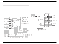
System Reset Circuit - main board
 |
UPC - 010343815766
View all Epson 2180 manuals
Add to My Manuals
Save this manual to your list of manuals |
Page 26 highlights
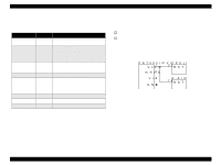
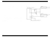
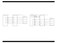
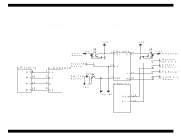
LQ-2180 The following table lists the each function of the main components of the C272 MAIN board. Table 2-1. Functions of the Main Board IC Name Location Function CPU IC4 Detects conditions of various sensors and controls phase change for the CR motor. Gate Array Control the functions below: • Memory management IC3 • Printhead drive • Phase change for the PF motor EEPROM Contains such information as the factory IC5 setting values for the various adjustments and the operational record of the printer. ROM IC10 Contains the control program. RAM Manages the following functions: • Buffer used to receive data IC8 • Data Extension • CPU working area CG-ROM IC7 Contains font data. SLA7024M IC11 Constant current drive IC for CR Motor A2917 IC12 Constant current drive IC for PF Motor Revision A 2.1.2 System Reset Circuit The reset IC (IC2) outputs a reset signal under the conditions below to feed back the status to the CPU and the gate array: † The printer is turned on or off. † The voltage level drops due to abnormal condition. Receiving the signal, the CPU and the gate array immediately shut off the operation of each IC to prevent the printer from falling into abnormal status caused by unstable power supply. P S T 5 9 2 (IC 2 ) V out 1 M RES 2 V cc 3 GND 4 C P U (IC 4 ) 2 3 /R S T G .A (IC 3 ) 7 4 /R S T Figure 2-3. Reset Circuit Operating Principles Control Circuit 26
-
 1
1 -
2
-
3
-
4
-
5
-
6
-
7
-
8
-
9
-
10
-
11
-
12
-
13
-
14
-
15
-
16
-
17
-
18
-
19
-
20
-
 21
21 -
 22
22 -
 23
23 -
 24
24 -
 25
25 -
 26
26 -
 27
27 -
 28
28 -
 29
29 -
 30
30 -
 31
31 -
32
-
33
-
34
-
35
-
36
-
37
-
38
-
39
-
40
-
41
-
42
-
43
-
44
-
45
-
46
-
47
-
48
-
49
-
50
-
51
-
52
-
53
-
54
-
55
-
56
 |
 |
