Contents
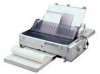
Product Description
Specifications
.................................................................................................
8
Features
................................................................................................................
8
Accessories
...........................................................................................................
8
Printing Specifications
...........................................................................................
9
Paper Handling
......................................................................................................
9
Paper Specifications
............................................................................................
11
Electrical Specifications
.......................................................................................
15
Reliability
.............................................................................................................
15
Safety Approvals
.................................................................................................
15
CE Marking
..........................................................................................................
15
Firmware Specifications
...............................................................................
16
Control Codes and Fonts
....................................................................................
16
Interface Specifications
.......................................................................................
18
Parallel Interface (Forward Channel)
..................................................
18
Parallel Interface (Reverse Channel)
.................................................
18
Operation Instruction
....................................................................................
19
Control Panel
.......................................................................................................
19
Bi-directional Adjustment Function
......................................................................
19
EEPROM Initialization
.........................................................................................
20
Main Components
.........................................................................................
21
C272MAIN Board
................................................................................................
22
Printer Mechanism
..............................................................................................
23
Operating Principles
Control Circuit
..............................................................................................
25
Overview of the Control Circuit Operation
...........................................................
25
System Reset Circuit
...........................................................................................
26
Printhead Driver Circuit
.......................................................................................
27
CR Motor Driver Circuit
.......................................................................................
28
PF Motor Driver Circuit
........................................................................................
28
EEPROM Control Circuit
.....................................................................................
29
Sensor Circuit
......................................................................................................
29
Disassembly and Assembly
Adjustment
Overview
......................................................................................................
33
Pre-operation for the Adjustment Program
.........................................................
33
Bi-D Adjustment
..................................................................................................
35
TPE Level Reset
.................................................................................................
36
Writing the User-characteristic Data
...................................................................
37
Troubleshooting
Overview
......................................................................................................
40
Troubleshooting Information
........................................................................
40
Printhead
.............................................................................................................
40
Sensors
...............................................................................................................
40
Motors
.................................................................................................................
40
Error Codes with Indicators and Buzzer
..............................................................
40
Unit Level Troubleshooting
...........................................................................
41
Repairing the C165 PSB/PSE Board
..............................................................
41
Repairing the C272MAIN Board
.....................................................................
41
Repairing the Printer Mechanism
..................................................................
43
Maintenance
Appendix
EEPROM Address Map
.................................................................................
47
Connector Summary
.....................................................................................
51
Component Layout
.......................................................................................
53
Circuit Diagram
............................................................................................
55
 1
1 2
2 3
3 4
4 5
5 6
6 7
7 8
8 9
9 10
10 11
11 12
12

