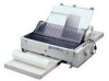
Epson 2180 Service Manual - Page 27
Printhead Driver Circuit - lq drivers
 |
UPC - 010343815766
View all Epson 2180 manuals
Add to My Manuals
Save this manual to your list of manuals |
Page 27 highlights
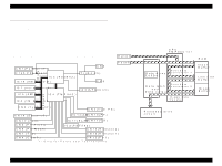
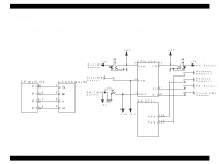
LQ-2180 2.1.3 Printhead Driver Circuit Printhead drive begins with monitoring the 35 V line currently applied. This function enables the printer to change the period of time for applying current to the printhead slightly depending on the condition. As a result, the printer can output image at a constant density. The Pin 74 (AN1) on the CPU monitors the 35 V line's condition. Also, when a high-duty job is in process, the temperature inside the printhead will rise, and if the job is continued at a high temperature, it may damage the coil. Therefore, the Pin 73 (AN0) on the CPU monitors the temperature inside the printhead. With this operation called protection operation for hot head, printing is stopped when the temperature reaches the standard level 1. As the temperature drops to the standard level 2, printing begins again at a lower speed, and then at a normal speed when the temperature lowers to the standard level 3. Once the current flows into the head drive resistor, the coil for the corresponding pin is activated with the current. The current flown into the coil is converted into energy used to rush the pin. Note there is possibility that some unused energy returns to the board, which may damage the head driver transistor. For this reason, a zener diode is attached for each transistor to ground the current so the voltage over the standard level (15 V) does not directly return to the transistor. Revision A E 0 5 B 4 2 (IC 3 ) HD1 Z D 2 -2 5 CN9 # 2 ,3 ,6 ,7 ,1 0 ,1 1 ,1 4 , 1 5 ,1 8 ,1 9 ,2 2 ,2 3 H D 24 73 AN0 A N 1 74 T r 4 -2 7 CN8 # 1 ,4 ,5 ,8 ,9 ,1 2 ,1 3 ,1 6 , 1 7 ,2 0 ,2 1 ,2 4 16 H TM P 35V Figure 2-4. Printhead Drive Circuit Operating Principles Control Circuit 27
-
 1
1 -
2
-
3
-
4
-
5
-
6
-
7
-
8
-
9
-
10
-
11
-
12
-
13
-
14
-
15
-
16
-
17
-
18
-
19
-
20
-
21
-
 22
22 -
 23
23 -
 24
24 -
 25
25 -
 26
26 -
 27
27 -
 28
28 -
 29
29 -
 30
30 -
 31
31 -
 32
32 -
33
-
34
-
35
-
36
-
37
-
38
-
39
-
40
-
41
-
42
-
43
-
44
-
45
-
46
-
47
-
48
-
49
-
50
-
51
-
52
-
53
-
54
-
55
-
56
 |
 |
