Epson 2180 Service Manual - Page 28
CR Motor Driver Circuit, PF Motor Driver Circuit - lq driver
 |
UPC - 010343815766
View all Epson 2180 manuals
Add to My Manuals
Save this manual to your list of manuals |
Page 28 highlights
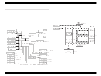
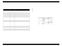
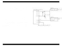
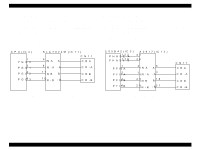
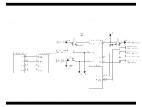
LQ-2180 2.1.4 CR Motor Driver Circuit The CPU (IC4) directly controls the phase change of the CR motor. SLA7024M (IC11), the driver IC for the CR motor, performs bi-polar constant current drive to detects the amount of current flowing into the motor and chops the current supplied. With this operation, current flowing into the motor coil is regulated. The CR motor driver circuit is as shown below: Revision A 2.1.5 PF Motor Driver Circuit The gate array (IC3) manages the PF motor control. The driver IC for the PF motor, which enables the constant current drive, receives the phase change signal directly from the gate array and determines the phase to which current flows. The PF motor driver circuit is as shown below: C P U (IC 4 ) 1 PG O 0 2 PG O 1 PG O 2 3 PG O 3 4 S L A 7 0 2 4 M (IC 1 1 ) 6 IN A A 5 IN -A -A 17 IN B B 16 IN -B -B C N 11 CRA C R -A CRB C R -B Figure 2-5. CR Motor Driver Circuit E 0 5 B 4 2 (IC 3 ) P H A S E A 122 P H A S E B 119 1 P F I0 A P F I1 A 2 P F I0 B 3 P F I1 B 4 A 2 9 1 7 (IC 1 2 ) 43 26 2 IN A 1 IN -A 23 IN B 2 4 IN -B 6 A 3 -A B 18 -B 2 1 C N 11 CRA C R -A CRB C R -B Figure 2-6. PF Motor Driver Circuit Operating Principles Control Circuit 28
-
 1
1 -
2
-
3
-
4
-
5
-
6
-
7
-
8
-
9
-
10
-
11
-
12
-
13
-
14
-
15
-
16
-
17
-
18
-
19
-
20
-
21
-
22
-
 23
23 -
 24
24 -
 25
25 -
 26
26 -
 27
27 -
 28
28 -
 29
29 -
 30
30 -
 31
31 -
 32
32 -
 33
33 -
34
-
35
-
36
-
37
-
38
-
39
-
40
-
41
-
42
-
43
-
44
-
45
-
46
-
47
-
48
-
49
-
50
-
51
-
52
-
53
-
54
-
55
-
56
 |
 |
