Epson LX-90 User Manual - Commodore 8691 PIC for LX-90 - Page 32
The Print Head, Graphics Mode, To keep the print head from leaving gaps between the graphics lines - ribbons
 |
View all Epson LX-90 manuals
Add to My Manuals
Save this manual to your list of manuals |
Page 32 highlights
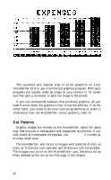
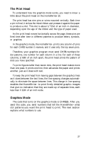
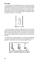
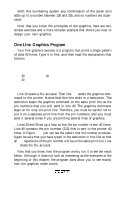
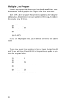
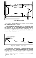
The Print Head To understand how the graphics mode works, you need to know a little about the print head on the HomeWriter-10. The print head has nine pins or wires mounted vertically. Each time a pin is fired, it strikes the inked ribbon and presses it against the paper to produce a dot. This dot is about 1/72nd of an inch in diameter, depending upon the age of the ribbon and the type of paper used. As the print head moves horizontally across the page, these pins are fired time after time in different patterns to produce letters, symbols, or graphics. In the graphics mode, the HomeWriter- prints one column of pins for each CHR$ number it receives, and it uses only the top seven pins. Therefore, your graphics program must send CHR$ numbers for dot patterns, one number for each column in a line. For each of those columns, 1/60th of an inch apart, the print head prints the pattern of dots you have specified. To print figures taller than seven dots, the print head makes more than one pass. It prints one line, then advances the paper and prints another, just as it does with text. To keep the print head from leaving gaps between the graphics lines as it does between the text lines, the line spacing changes automatically to eliminate the space between lines. This change in line spacing enables the HomeWriter- to print finely detailed graphic images that give no indication that they are made up of separate lines, each less than l/10th of an inch wide. Graphics Mode The code that turns on the graphics mode is CHR$(8). After you send this code, you send numbers that tell the HomeWriter- what dot patterns you want the print head to print. The next section explains what numbers to use. 27
-
 1
1 -
2
-
3
-
4
-
5
-
6
-
7
-
8
-
9
-
10
-
11
-
12
-
13
-
14
-
15
-
16
-
17
-
18
-
19
-
20
-
21
-
22
-
23
-
24
-
25
-
26
-
 27
27 -
 28
28 -
 29
29 -
 30
30 -
 31
31 -
 32
32 -
 33
33 -
 34
34 -
 35
35 -
 36
36 -
 37
37 -
38
-
39
-
40
-
41
-
42
-
43
-
44
-
45
-
46
-
47
-
48
-
49
-
50
-
51
-
52
-
53
-
54
-
55
-
56
-
57
-
58
-
59
 |
 |