Epson MX-80 F/T User Manual
Epson MX-80 F/T - Impact Printer Manual
 |
View all Epson MX-80 F/T manuals
Add to My Manuals
Save this manual to your list of manuals |
Epson MX-80 F/T manual content summary:
- Epson MX-80 F/T | User Manual - Page 1
MX-80F/T EPSON DOT MATRIX PRINTER r Operation Manual 3 EPSON P8093033-1 - Epson MX-80 F/T | User Manual - Page 2
Copyright 0 1981 by EPSON, Shinshu Seiki Co., Ltd. Nagano, Japan "All rights reserved" *The contents of this manual are subject to change without notice. TRS-80 is the registered trademark of Radio Shack, a Division of Tandy Corporation. - Epson MX-80 F/T | User Manual - Page 3
OPERATION 1. Switches and Indicators 1.1. Switches 1.2. Indicators 2. Buzzer 3. Paper End Detector 4. Self-Test 5. Construction of MX-80 F/T 5.1. Printer mechanism 5.2. Control circuit board 5.3. Power circuit 5.4. Printer initialization 6. Setting of DIP Switches 7. Parallel - Epson MX-80 F/T | User Manual - Page 4
MAINTENANCE 44 1. Preventive Maintenance 44 2. Parts Replacement 44 SPECIFICATIONS 46 SUMMARY OF CONTROL CODES 48 APPENDIX 49 Assembly Instructions on Roll Paper Holder 49 -(2)-- - Epson MX-80 F/T | User Manual - Page 5
LIST OF FIGURES Fig. 1 EPSON MX-80 F/T Dot Matrix Printer 1 Fig. 2 Contents of Carton 2 Fig. 3 Removal of Shipping Screws 4 Fig. 4 Removal of Printer Lid 5 Fig. 5 Cartridge Ribbon Setting 6 Fig. 6 Cartridge Ribbon Setting 6 - Epson MX-80 F/T | User Manual - Page 6
Pins 2-1 and 2-2 28 Table 5 Connector Pin Assignment and Descriptions of Interface Signals. 29 Table5 (cont 30 Table 6 Coding Table (Standard 32 Table 7 Coding Table (TRS-80 33 Table 6 Special Characters/Symbols 34 Table 9 DC 1 /DC3 and Data Entry 38 -(4)- - Epson MX-80 F/T | User Manual - Page 7
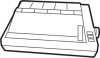
INTRODUCTION The EPSON MX-80 F/T Dot Matrix Printer is a highly versatile, general-purpose and computer-grade printer featuring 80 CPS bi-directional printing with logical seeking capability and 9 X 9 dot-matrix character formation. The MX-80 F/T accepts the ASCII 96 codes and codes for special - Epson MX-80 F/T | User Manual - Page 8
any listed contents missing or evident damage. contact the store where you purchased the MX-80 F/T as soon as possible. 1 Power Cord (European Type) Operation Manual MX-80 F/T Dot Matrix Printer 1. MX-80 F/T 1 2. Separator 1 3. Cartridge Ribbon 1 4. Power Cord (Only European Type 220/240V - Epson MX-80 F/T | User Manual - Page 9
the Printer (1) Operating site selection When installing the MX-80 F/T, observe the following instructions. (a) Place the Printer on a bench, tabletop not subject the Printer to temperatures below 5°C (4O'F) or above 35°C (95'F) during operation, to sudden changes in temperature, or to extreme shock. - Epson MX-80 F/T | User Manual - Page 10
with a protective paper inserted between the inner and outer paper guides to protect the paper end detector from damage due to shocks or vibrations during transportation. Before using the Printer, be sure to remove this paper. If the MX-80 F/T is to be reshipped. remember to return it to the - Epson MX-80 F/T | User Manual - Page 11
Printer Lid (1) Standard (2) Option Fig. 4 Removal of Printer Lid NOTE: The printer lid shown in Fig. 4 (2) is an optional accessory. -5- - Epson MX-80 F/T | User Manual - Page 12
4. Cartridge Ribbon Setting EPSON's Cartridge Ribbon is compact, long-lasting, and very easy to set and remove. Furthermore, you have no need to soil your fingers in handling it. - Epson MX-80 F/T | User Manual - Page 13
NOTES: 1. Incorrect setting of the ribbon may cause it to come off. (See Fig. 7.) 2. Confirm that the ribbon is neither twisted nor creased and that the cartridge is set properly. Ribbon Mask Incorrect Incorrect Correct Fig. 7 Examples of Correct and Incorrect Ribbon Setting 5. Separator - Epson MX-80 F/T | User Manual - Page 14
6. Dismounting of Tractor Unit The tractor unit of the MX-80 F/T is detachable. If it is an obstacle when using roll paper, it can be taken out as follows; STEP 1. Release the lock levers of the - Epson MX-80 F/T | User Manual - Page 15
Paper Loading 7.1. Fanfold paper 7.1.1. Loading of fanfold paper The MX-80 F/T Printer accommodates fanfold paper from 4" to 10" in width Printer to detach the scale from the platen. STEP 4. Confirm that the paper guide roller is at the center of the sprocket shaft, If not, set it at the center of - Epson MX-80 F/T | User Manual - Page 16
STEP 8. Raise the two sprocket lock levers to loosen, and adjust the sprocket pin position to the paper width. (See Fig. 12.) Paper Holding Cover ket Lock Lever Fig. 12 Raising of Sprocket Lock Levers , STEP 9. Engage the paper feed holes of the paper on the feeding pins, push the scale back into - Epson MX-80 F/T | User Manual - Page 17
the Printer. (See Fig. 14.) I Fig. 14 Printer with Fanfold Paper Set Completely NOTE: When the MX-80 F/T is to be used on a desk or a bench, arrangement of the fanfold paper in parallel with the MX-80 F/T as shown below will permit the paper to be folded in an accordion style. Course of Paper - Epson MX-80 F/T | User Manual - Page 18
power switch is turned on. Namely, adjust the paper position by the manual paper feed knob so that the required line position (i.e., the point at case of feeding one page of fanfold paper by operating the MX-80 F/T by the input of FF code, the abovementioned adjustment is effective. Matchmark - - Epson MX-80 F/T | User Manual - Page 19
7.2. Roll Paper 7.2.1. Roll paper holder EPSON offers the roll paper holder as an optional accessory for the MX-80 F/T. See Appendix for the assembly instructions on Roll Paper Holder. 7.2.2. Loading of roll paper The MX-80 F/T accommodates a roll of single ply paper measuring 8.5f0.12 in. in width - Epson MX-80 F/T | User Manual - Page 20
(2) Roll Paper Manual Paper Feed Knob Fig. 19 Loading of Roll Paper (3) 7.3. Cut paper sheet 7.3.1. Loading of cut paper sheet The MX-80 F/T accommodates cut paper platen. (See Fig. 20.) STEP 4. Confirm that the paper guide roller is at the center of the sprocket shaft. If not, set it at the - Epson MX-80 F/T | User Manual - Page 21
Fig. 20 Loading of Cut Paper Sheet STEP 6. Lock the release lever. STEP 7. While turning the manual paper feed knob clockwise, confirm that the paper advances straight up. (See Fig. 21.) Manual Paper Feed Knob Fig. 21 Adjustment of Inserted Paper Position If not, adjust the inserted paper position - Epson MX-80 F/T | User Manual - Page 22
Fig. 22 Alignment of Side edges (b) If the cut paper sheet or form is not long enough to align the side edges, align the top edge of the paper with the form position setting mark on the tractor unit. (See Fig. 23.) , l/s I - 1 i. l/4 I Fig. 23 Form Position Setting Mark The print area on the - Epson MX-80 F/T | User Manual - Page 23
4, +...-- Letter Size Paper---+ ; rA4SizePaperpf /4 Fig. 25 Setting of Cut Paper Sheet I Fig. 26 Printer with Cut Paper Sheet Set Completely NOTES: 1. The Paper End Detector function may be disabled under software control (ESC 8; refer to page 39) provided printing is left off within 7.5 mm - Epson MX-80 F/T | User Manual - Page 24
sheets is used, be sure that no characters are printed within the area two lines each above and below the perforation. 9. Power Connection The EPSON MX-80 F/T Dot Matrix Printer is capable of operating on the following three types of AC power. (1) 115V AC, 60Hz (2) 220V AC, 50Hz (3) 240V AC, 50Hz - Epson MX-80 F/T | User Manual - Page 25
Head Adjusting Le @Backward _ Fotward @ Head Adjusting Lever 4th step Fig. 27 Gap Adjustment 7th step -19- - Epson MX-80 F/T | User Manual - Page 26
OPERATION 1. Switches and indicators There are three switches and four indicators (green LED's) on the control panel and one power switch on the right side of the Printer case. In this section, panel operating procedures are covered in sufficient detail for the user to become familiarized with the - Epson MX-80 F/T | User Manual - Page 27
) OFF stops the buzzer from sounding under the above condi- I tions. 3. Paper End Detector When the paper end detector (a reed switch located on the paper guide) detects that the paper is nearly exhausted, the signals on the interface connector change to the following statuses. -21- - Epson MX-80 F/T | User Manual - Page 28
apply the m signal. In this case, however, all previously established data such as TAB, line spacing, etc. are erased. 4. Self-Test The MX-80 F/T has a self-test (self-diagnostic) function to check the following. (1) Print head operation and printing quality (2) Operation of the printer mechanisms - Epson MX-80 F/T | User Manual - Page 29
.) l Example of printing'?" "Z"=[5. A]~=(0101 1010) In this case, connect pin Nos. 2, 4, 7 and 9 to pin No. 33. 5. Construction of MX-80 F/T The EPSON MX-80 F/T Dot Matrix Printer consists of the following three major functional blocks. (1) The model 3310 printer mechanism (2) Control circuit board - Epson MX-80 F/T | User Manual - Page 30
5.2. Control circuit board In this paragraph, the printer LSI circuitry is outlined. The control circuit diagram is shown 'in Fig. 29, and the driver circuit diagram in Fig. 30. Fig. 29 Control Circuit Diagram -24- - Epson MX-80 F/T | User Manual - Page 31
HI 0 Hz 0 9 X 2SD986 m I H, 0 D H, 0 1 "s 0 > H, 0 D H, 0 m He 0 D H9 O- Fig. 30 Driver Circuit Diagram -25- - Epson MX-80 F/T | User Manual - Page 32
5.3. Power circuit The power circuit generates 5V DC for the logic circuit, and 24V DC to energize the solenoids of the print head and two stepper motors. 5.4. Printer initialization Printer initialization is accomplished in either of the two ways described below. (1) Initialization takes place - Epson MX-80 F/T | User Manual - Page 33
8. Setting of DIP Switches There are two DIP switches on the control circuit board. In order to suit the user's specific requirements, desired control modes are selectable by the DIP switches. The functions of the switches and their preset conditions at the time of shipment are as shown in Table 2 ( - Epson MX-80 F/T | User Manual - Page 34
2-2) SW2-1 ON ON OFF I OFF SW 2-2 ON OFF 1 ON OFF Country U.S.A. France Germany England I 7. Parallel Interface The MX-80 F/T includes a parallel interface as the standard equipment, and this paragraph describes the parallel interface. (1) Specifications (a) Data transfer rate - Epson MX-80 F/T | User Manual - Page 35
Table 5 Connector Pin Assignment and Descriptions of Interface Signals STROBE pulse to read data in. Pulse width These signals represent information of the 1st to 8th bits of parallel data respectively. Each signal is at "HIGH" level when data is logical "1" and "LOW" when logical "0". A "HIGH" - Epson MX-80 F/T | User Manual - Page 36
Signal Return Pin No. ! Pin No. I 18 - -9 to30 - 31 - 32 33 - 34 - 35 36 - Signal Table 5 (cont.) - IDirection Description NC GND lNlT In -- ERROR out GND - NC SLCT IN In Not used. TWISTED-PAIR RETURN signal GND level. When the level of this signal becomes "LOW", the - Epson MX-80 F/T | User Manual - Page 37
the OFF position. (2) When the DIP switch pin 2-4 is turned ON, the Printer behaves as a completely compatible printer to the Tandy Personal Computer TRS-80. The available codes in this case are shown in Table 7. Note that all the other pins of DIP switches 1 and 2 will not function irrespective of - Epson MX-80 F/T | User Manual - Page 38
8 1000 CAN ( 8 H X h x CAN 9 1001 HT ) 9 I Y i Y HT A 1010 LF 5 : J Z j z LF B 1011 VT ESC + ; K t k C I VT ESC p L 1 I L\ 1 i D 1101 CR = M 3 m ) CR E 1110 so . > N ..x n * so F 1111 SI / ? 0 - --0 DEL SI ' - Epson MX-80 F/T | User Manual - Page 39
D 1101 CR GS - = M 3 m E 1110 RS . > N .+ n * F 1111 us / ? 0 - 0 DEL : 16.5 charalinch 5 charalinch print -ESC 6 : 6 lines/inch line feed i -ESC 8 : 8 lines/inch line feed 1 -ESC A : Long line mode 1 .ESC B : Short line mode I ti - Epson MX-80 F/T | User Manual - Page 40
ii j [7E] H - " P 9. Control Codes Various kinds of control codes are contained in Tables 6 and 7. These control codes are recognized by the MX-80 F/T, and the Printer performs specified functions upon receipt of these codes. The following are descriptions of respective control codes. (1) CR - Epson MX-80 F/T | User Manual - Page 41
(2) LF (Line Feed) When the LF code is input, all data in the print buffer is printed and the paper is advanced one line. NOTE: If no data precedes the LF code, or if all preceding data is "SPACE", only paper feeding is performed. For example, if the data is transferred in the order of DATA-+CR+ LF. - Epson MX-80 F/T | User Manual - Page 42
(6) SI (Shift In) When the SI code is input, all data that follows it will be printed out in condensed characters. This code is cancelled by the input of "DC 2" code. The SI code can be input at any column position on a line, but all characters/ symbols on the line containing SI code are printed out - Epson MX-80 F/T | User Manual - Page 43
(10) CAN (Cancel) Upon the input of the CAN code, all data previously stored in the print buffer is cancelled. Therefore, this code is regarded as the print buffer clear command. This code clears the print buffer, but control codes (excluding the SO code) are still valid even if the CAN code is - Epson MX-80 F/T | User Manual - Page 44
Relations among the ON LINE switch, SLCT IN signal, DC l/DC 3 code and interface signals are shown in Table 9 below. Table 9 DC 1/DC 3 and Data Entry NOTES: 1. In Table 9, it is assumed that as soon as the Printer receives data. it sends back the ACKNLG signal, though this data is not stored in the - Epson MX-80 F/T | User Manual - Page 45
2) ESC 1 (Escape 1) Receipt of an "ESC" followed by ASCII code "1" causes the line spacing to be set at 7/72 inch. Input of the ESC 2 code or INIT signal to the interface connector or turning the power off and on again causes the line spacing to return to l/6 inch. 3) ESC 2(Escape 2) Receipt of an " - Epson MX-80 F/T | User Manual - Page 46
the keyboard of a host computer is different, for which refer to the specifications of your host computer. *Example: Input from the keyboard of the TRS-80 personal computer. [LPRINT CHR$(27); CHR$(65); CHR$(24)] -40- - Epson MX-80 F/T | User Manual - Page 47
2 ) E S C B+nl+n2+. +nk+NUL (ldlo - Epson MX-80 F/T | User Manual - Page 48
. Tab stop numbers must be received in incremental numerical order. If a tab stop position of higher value than 80 is received in normal character printing mode, all horizontal tab functions after 80 columns are ignored. To execute tab stop positions, the HT code should be input. The HT code is - Epson MX-80 F/T | User Manual - Page 49
5) ESC E The ESC E code causes the Printer to print emphasized characters. Emphasized printing gives the character a stronger impression on the paper. This code can be input in any column position on a line. The speed of the head carriage reduces to 40 CPS while printing emphasized characters. 1. [ - Epson MX-80 F/T | User Manual - Page 50
of the circuitry and mechanisms utilized in the MX-80 F/T, operator's troubleshooting is logically obliged to be limited to certain the operator should contact the store from which the MX-80 F/T was purchased. (2) Print head In case of a print head trouble or a worn dot wire, replace the print head - Epson MX-80 F/T | User Manual - Page 51
Head Print Head Unit Cable ! Head Lock Terminal Board / Head Connector 'Be sure to hold this connector firmly to pull the head cable out straight. (Side View) 'Take hold of the cable at the point ijjdicated by arrows e and apply force in either of the directions indicated by arrow M to push in - Epson MX-80 F/T | User Manual - Page 52
inch per line Normal: 10 80 Enlarged: 5 40 Condensed: 16 HANDLING Paper Feed: Friction feed or adjustable sprocket feed selectable manually Paper Width Range Fanfold paper: 101.6 mm (4") to print head) (12) ENVIRONMENTAL CONDITIONS Operating Temperature Range: 5 to 35°C (41 to 95°F) - Epson MX-80 F/T | User Manual - Page 53
SPECIFICATIONS (continued) (13) POWER REQUIREMENT Voltage: 115V. 60 Hz 220/240V, 50 Hz Current: 1 Amp maximum Power Consumption: 100 VA maximum (14) PHYSICAL CHARACTERISTICS Height: 133 mm (5.2") W idth: 374 mm (14.7") Depth: 305 mm (12.0") Weight: 7.0 kg (15.4 Ibs.) I - Epson MX-80 F/T | User Manual - Page 54
data lines. Control codes are sent as data, and are interpreted as instructions by the Printer. The following is a summary of control codes and control code sequences recognized by the MX-80 F/T. (1) Print action codes M n e m o n i c D e c i m a l Hex. code Function CR 13 0D Performs the - Epson MX-80 F/T | User Manual - Page 55
APPENDIX Assembly Instructions on Roll Paper Holder 1. Confirm that all the component parts shown in Fig. 1 are contained in the carton. Part name A Stand. B Shaft C Base plate D Arc bearing. E Screw grommet. F Tension lever. . . G Guide roller . . QW 1 .1 1 2 . . . .. 2 .. .1 2 Fig. 1 - Epson MX-80 F/T | User Manual - Page 56
3. Put base plate C on stand A and secure it by inserting two screw grommets E to the corresponding square holes as shown in Fig. 3. In this case, take note of the direction in which base plate C must be placed on the stand. I Fig. 3 Mounting of Base Plate on Stand 4. Set tension lever F on stand - Epson MX-80 F/T | User Manual - Page 57
6. Set the Roll Paper Holder to the Printer by aligning the base plate with the knots located at the bottom of the printer. Fig. 6 7. Fig. 7 shows how to insert shaft B into the core of the roll paper. I I Fig. 7 Insertion of Shaft B into Roll Paper Core 8. Fig. 8 shows the Printer with the Roll - Epson MX-80 F/T | User Manual - Page 58
FEDERAL COMMUNICATIONS COMMISSION RADIO FREQUENCY INTERFERENCE STATEMENT "Warning: This equipment has been certified to comply with the limits for a Class B computing device, pursuant to Subpart J of Part 15 of FCC Rules. Only computers certified to comply with the Class B limits may be attached to - Epson MX-80 F/T | User Manual - Page 59
98 Cutter Mill Road Great Neck, New York Phone: (516)487-0660 Telex: (25)510223-0743 EPSON DEUTSCHLAND GMBH Am Seestern 24 4000 Dtisseldorf 11, F.R. Germany Phone: 0211-593080 Telex: (41)8584786 EPSON U.K. LTD. Sherwood House 176 Northolt Road South Harrow HA2 OEB U.K. Phone: (01) 422-5612 Telex
-
 1
1 -
 2
2 -
 3
3 -
 4
4 -
 5
5 -
 6
6 -
 7
7 -
8
-
9
-
10
-
11
-
12
-
13
-
14
-
15
-
16
-
17
-
18
-
19
-
20
-
21
-
22
-
23
-
24
-
25
-
26
-
27
-
28
-
29
-
30
-
31
-
32
-
33
-
34
-
35
-
36
-
37
-
38
-
39
-
40
-
41
-
42
-
43
-
44
-
45
-
46
-
47
-
48
-
49
-
50
-
51
-
52
-
53
-
54
-
55
-
56
-
57
-
58
-
59
 |
 |
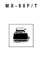
MX-80F/T
EPSON DOT MATRIX PRINTER
Operation Manual
r
3
EPSON
P8093033-1