Frigidaire GLEH1642FS Installation Instructions (All Languages) - Page 5
Gas Supply Requirements, Location Of Your Laundry Center
 |
UPC - 012505376368
View all Frigidaire GLEH1642FS manuals
Add to My Manuals
Save this manual to your list of manuals |
Page 5 highlights
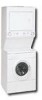
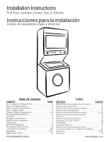
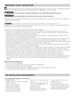
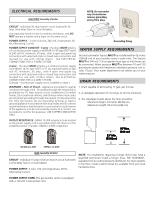
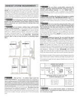
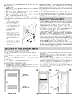
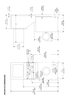
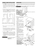
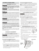
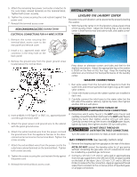
The laundry center may be exhausted four (4) ways with rear flush installation: 1. Straight back 2. Down (8 inch [20.32 cm] length of 4 inch [10.16 cm] rigid duct and 1 elbow down) 3. Left (8 inch [20.32 cm] length of 4 inch [10.16 cm] rigid duct, 1 elbow down and 1 elbow left) 4. Right (8 inch [20.32 cm] length of 4 inch [10.16 cm] rigid duct, 1 elbow down and 1 elbow right) Although vertical orientation of the exhaust system is acceptable, certain extenuating circumstances could affect the performance of the dryer: • Only the rigid metal duct work should be used. • Venting vertical through a roof may expose the exhaust system to down drafts causing an increase in vent restriction. • Running the exhaust system through an uninsulated area may cause condensation and faster accumulation of lint. • Compression or crimping of the exhaust system will cause an increase in vent restriction. To exhaust up, add an 11 inch (27.94 cm) length of standard 4 inch (10.16 cm) diameter duct and a 90° elbow. The unit will be positioned about 4½ inches (11.43 cm) away from the wall (flush to wall exhausting may be done by going below the dryer then sideways). An exhaust hood positioned to line up with the dryer exhaust can be installed directly through the outside wall. To exhaust to the side or down, add an 8 inch (20.32 cm) length of standard 4 inch (10.16 cm) diameter duct and a 90° elbow. GAS SUPPLY REQUIREMENTS 1.Installation MUST conform with local codes, or in the absence of local codes, with the National Fuel Gas Code, ANSI Z223.1 (latest edition) or in Canada, the current AN/CGA B149. 2.The gas supply line should be of 1/2 inch (1.27 cm) pipe. 3.If codes allow, flexible metal tubing may be used to connect your dryer to the gas supply line. The tubing MUST be constructed of stainless steel or plastic-coated brass. 4.The gas supply line MUST have an individual shutoff valve. 5.A 1/8 inch (0.32 cm) N. P. T. plugged tapping, accessible for test gage connection, MUST be installed immediately upstream of the gas supply connection to the dryer. 6.The dryer and its individual shutoff valve MUST be disconnected from the gas supply piping system during any pressure testing of the gas supply piping system at test pressures equal to or less than 1/2 psig (3.45 kPa). 7.The dryer MUST be isolated from the gas supply piping system by closing its individual manual shutoff valve during any pressure testing of the gas supply piping system at test pressures equal to or less than 1/2 psig (3.45 kPa). LOCATION OF YOUR LAUNDRY CENTER DO NOT INSTALL YOUR LAUNDRY CENTER: 1. In an area exposed to dripping water or outside weather 3. Your laundry center needs the space around it for proper conditions. ventilation. 2. In an area where it will come in contact with curtains or drapes. 3. On carpet. Floor MUST be solid with a maximum slope of 1 inch (2.54 cm). 4. On a pedestal. Excessive vibration can occur. DO NOT INSTALL YOUR LAUNDRY CENTER IN A CLOSET WITH A SOLID DOOR. 4. A minimum of 120 square inches (774.2 square cm) of opening, equally divided at the top and bottom of the door, is required. Air openings are required to be unobstructed when a door is installed. A louvered door with equivalent air INSTALLATION IN RECESS OR CLOSET 1. A laundry center installed in a bedroom, bathroom, recess or closet, MUST be exhausted outdoors. 2. No other fuel burning appliance shall be installed in the same openings for the full length of the door is acceptable. 5. The following illustrations show minimum clearance dimensions and air openings for proper operation in a recess or closet installation. closet as the Gas laundry center. 0 IN. (0 CM) 0 IN. (0 CM) 1 IN. (2.54 CM) 0 IN. (0 CM) 60 SQ. IN. (387.1 SQ. C M) 60 SQ. IN. (387.1 SQ. CM) DRYER 60 SQ. IN. (387.1 SQ. C M) Closet Door 5 WASHER 60 SQ. IN. (387.1 SQ. CM)
-
 1
1 -
 2
2 -
 3
3 -
 4
4 -
 5
5 -
 6
6 -
 7
7 -
 8
8 -
 9
9 -
 10
10 -
 11
11 -
12
-
13
-
14
-
15
-
16
-
17
-
18
-
19
-
20
 |
 |