Frigidaire GLEH1642FS Installation Instructions (All Languages) - Page 9
Installation - white
 |
UPC - 012505376368
View all Frigidaire GLEH1642FS manuals
Add to My Manuals
Save this manual to your list of manuals |
Page 9 highlights
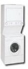
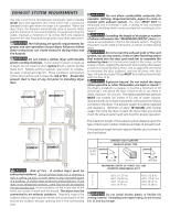
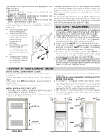
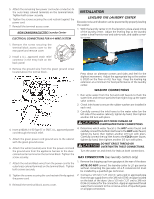
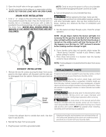
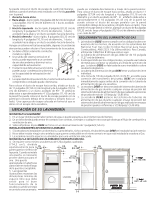
5. Attach the remaining two power cord outer conductors to the outer brass colored terminals on the terminal block. Tighten both screw securely. 6. Tighten the screws securing the cord restraint against the power cord. 7. Reinstall the terminal access cover. NON-CANADIAN ELECTRIC Laundry Center ELECTRICAL CONNECTIONS FOR A 4-WIRE SYSTEM INSTALLATION LEVELING THE LAUNDRY CENTER Excessive noise and vibration can be prevented by properly leveling the washer. 1. With the laundry center in it's final position, place a level ontop of the laundry center. Adjust the leveling legs so the laundry center is level front-to-rear and side-to-side, and stable cornerto-corner. 1. Remove the screw securing the terminal block access cover to the rear panel and remove cover. 2. Install a U.L. approved strain relief connector in the entry hole on the back panel. 3. Remove the ground wire from the green ground screw located above the termial block. Press down on alternate corners and sides and feel for the slightest movement. Adjust the appropriate leg so the washer is SOLID on the floor on ALL four legs. Keep the leveling leg extension at a minimum for best performance of the laundry center. WASHER CONNECTIONS 4. Insert a NEMA 14-30 Type ST or SRDT, U.L. approved power cord through the strain relief. 5. Attach the green power cord ground wire to the cabinet with the green ground screw. 6. Attach the white (neutral) wire from the power cord and the ground wire from the appliance harness to the silvercolored center terminal on the terminal block. Tighten the screw securely. 7. Attach the red and black wires from the power cord to the outer brass-colored terminals on the terminal block. Tighten both screws securely. 8. Tighten the screws securing the cord restraint firmly against the power cord. 9. Reinstall the terminal block access cover. 1. Run some water from the hot and cold faucets to flush the water lines and remove particles that might clog up the water valve screens. 2. Check inlet hoses to ensure the rubber washers are installed in each end. 3. Carefully connect the inlet hoses to the water valve (on the left side of the washer cabinet), tighten by hand, then tighten another 2/3 turn with pliers. C AUT ION DO NOT CROSS THREAD OR OVERTIGHTEN THESE CONNECTIONS. 4. Determine which water faucet is the HOT water faucet and carefully connect the bottom inlet hose to the HOT water faucet, tighten by hand, then tighten another 2/3 turn with pliers. Carefully connect the top inlet hose to the COLD water faucet, tighten by hand, then tighten another 2/3 turn with pliers. CAUTION DO NOT CROSS THREAD OR OVERTIGHTEN THESE CONNECTIONS. Turn the water on and check for leaks at both connections. GAS CONNECTION (Gas laundry centers only) 1. Remove the shipping cap from gas pipe at the rear of the dryer. NOTE: DO NOT connect the laundry center to L.P. gas service without converting the gas valve. An L.P. conversion kit must be installed by a qualified gas technician. 2. Connect a 1/2 inch (1.27 cm) I.D. semi-rigid or approved pipe from the gas supply line to the 3/8 inch (0.96 cm) pipe located on the back of the dryer. Use a 1/2 inch (1.27 cm) to 3/8 inch (0.96 cm) reducer for the connection. Apply an approved thread sealer that is resistant to the corrosive action of liquefied gases on all pipe connections.
-
 1
1 -
2
-
3
-
 4
4 -
 5
5 -
 6
6 -
 7
7 -
 8
8 -
 9
9 -
 10
10 -
 11
11 -
 12
12 -
 13
13 -
 14
14 -
15
-
16
-
17
-
18
-
19
-
20
 |
 |