Garmin Compact Reactor 40 Hydraulic Autopilot with GHC 20 and Shadow Drive Pack - Page 1
Garmin Compact Reactor 40 Hydraulic Autopilot with GHC 20 and Shadow Drive Pack Manual
 |
View all Garmin Compact Reactor 40 Hydraulic Autopilot with GHC 20 and Shadow Drive Pack manuals
Add to My Manuals
Save this manual to your list of manuals |
Page 1 highlights
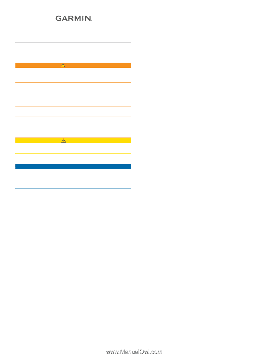
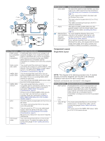
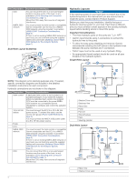
REACTOR™ 40 COMPACT HYDRAULIC Installation Instructions Important Safety Information WARNING See the Important Safety and Product Information guide in the product box for product warnings and other important information. You are responsible for the safe and prudent operation of your vessel. The autopilot is a tool that enhances your capability to operate your boat. It does not relieve you of the responsibility of safely operating your boat. Avoid navigational hazards and never leave the helm unattended. Always be prepared to promptly regain manual control of your boat. Learn to operate the autopilot on calm and hazard-free open water. Use caution when operating the autopilot near hazards in the water, such as docks, pilings, and other boats. CAUTION When in use, beware of hot motor and solenoid components and the risk of entrapment from moving parts. Failure to install and maintain this equipment in accordance with these instructions could result in damage or injury. NOTICE To avoid damage to your boat, the autopilot system should be installed by a qualified marine installer. Specific knowledge of hydraulic steering componentry and marine electrical systems is required for proper installation. Registering Your Device Help us better support you by completing our online registration today. Keep the original sales receipt, or a photocopy, in a safe place. 1 Go to garmin.com/express . 2 Sign in to your Garmin® account. Installation Preparation The autopilot system consists of multiple components. You should familiarize yourself with all of the component mounting and connection considerations before beginning installation. You must know how the components operate together in order to correctly plan the installation on your boat. You can consult the layout diagrams (Power and Data Layout, page 2) to help understand the mounting and connection considerations. You should lay out all of the components on the boat as you plan the installation to make sure your cables will reach each component. If needed, extension cables (sold separately) for various components are available from your Garmin dealer or from www.garmin.com. You should record the serial number of each component for registration and warranty purposes. Tools Needed • Safety glasses • Drill and drill bits • Wrenches • 90 mm (3.5 in.) hole saw or a rotary cutting tool (for installing an optional helm control) • Wire cutters/strippers • Phillips and flat screwdrivers • Cable ties • Single Pole Single Throw (SPST) switch (to use as an autopilot bypass when not installing the Shadow Drive™ valve) • Waterproof wire connectors (wire nuts) or heat-shrink tubing and a heat gun • Marine sealant • Marine corrosion inhibitor spray • Portable or handheld compass (to test for magnetic interference) • Hydraulic hose with machine-crimped or field-replaceable fittings that have a minimum rating of 1000 psi • Hydraulic T-fittings • Hydraulic fluid • Thread sealant • Hydraulic bleeding equipment NOTE: Mounting screws are provided for the main components of the autopilot system. If the provided screws are not appropriate for the mounting surface, you must provide the correct types of screws. Mounting and Connection Considerations The autopilot components connect to each other and to power using the included cables. Ensure that the correct cables reach each component and that each component is in an acceptable location before mounting or wiring any components. CCU Mounting and Connection Considerations • The CCU is the primary sensor of the Reactor 40 Compact Hydraulic autopilot system. For best performance, observe these considerations when selecting a mounting location. ◦ A handheld compass should be used to test for magnetic interference in the area where the CCU is to be mounted(Testing a Location for Magnetic Interference, page 2). ◦ The CCU should be mounted on a rigid surface for best performance. • Mounting screws are provided with the CCU. If you use mounting hardware other than the provided screws, the hardware must be quality stainless or brass material to avoid magnetic interference with the CCU. Test any mounting hardware with a handheld compass to make sure no magnetic fields are present in the hardware. • The CCU cable connects the CCU to the ECU and is 5 m (16 ft.) long. ◦ If the CCU cannot be mounted within 5 m (16 ft.) of the ECU, extension cables are available from your local Garmin dealer or at www.garmin.com. ◦ This cable must not be cut. Finding the Best Mounting Location 1 Create a list of all suitable mounting locations for the CCU. Suitable mounting locations should not be within 60 cm (2 ft.) of the following: • Iron • Magnets • High-current wires • Intermittently-running pumps, such as head pumps and live well pumps A large magnet, such as a subwoofer-speaker magnet, should be no closer than 1.5 m (5 ft.) to any of the mounting locations. October 2017 190-02316-02_0A
-
 1
1 -
 2
2 -
 3
3 -
 4
4 -
 5
5 -
 6
6 -
 7
7 -
8
-
9
-
10
-
11
-
12
 |
 |