Garmin Compact Reactor 40 Hydraulic Autopilot with GHC 20 and Shadow Drive Pack - Page 8
Configuration, Appendix
 |
View all Garmin Compact Reactor 40 Hydraulic Autopilot with GHC 20 and Shadow Drive Pack manuals
Add to My Manuals
Save this manual to your list of manuals |
Page 8 highlights
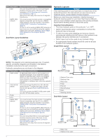
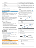
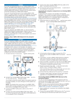
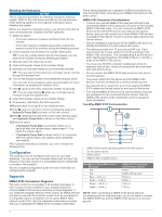
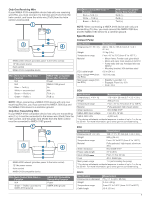
Bleeding the Hydraulics NOTICE This is a general procedure for bleeding a hydraulic steering system. Refer to the instructions provided by the manufacturer of the steering system for more-specific information about bleeding the system. Before you bleed the hydraulic system, you should verify that all hose connections are complete and fully tightened. 1 Select an option: • If the helm reservoir contains insufficient fluid, fill it as needed. • If the helm reservoir contains excess fluid, remove the excess to avoid fluid overflow during the bleeding process. 2 Insert a bypass hose between the cylinder bleed ports. TIP: If you use a clear plastic hose for this bypass, you can observe air bubbles during the bleeding processes. 3 Manually steer the helm fully to port. 4 Open both bypass valves at the cylinder fittings. 5 Manually turn the helm slowly to port over three minutes. TIP: You can stop turning when you no longer see air moving through the bypass hose. 6 Turn on the autopilot system and disable the Shadow Drive. You can refer to the autopilot system documentation for more information on disabling the Shadow Drive. 7 Hold (port) on the helm control for at least 10 seconds. TIP: You can stop holding when you no longer see air moving through the bypass hose. 8 Close both bypass valves at the cylinder fittings. 9 If necessary, add fluid to the helm reservoir. 10Repeat steps 3 through 9 for the starboard side. 11Hold (port) on the helm control until steering stops and Hydraulic Pump Stall is shown on the helm control. 12Hold (starboard) on the helm control until steering stops and Hydraulic Pump Stall is shown on the helm control. 13Select an option: • If Hydraulic Pump Stall is not shown within 2 to 3 seconds after the cylinder stops, repeat steps 1-13 to bleed the system again. • If Hydraulic Pump Stall is shown within 2 to 3 seconds after the cylinder stops, the system bleed completed successfully. After hydraulic bleeding is complete, you can re-enable the Shadow Drive. Configuration The autopilot must be configured and tuned to your boat dynamics. You can use the Dockside Wizard and the Sea Trial Wizard on the helm control or a compatible Garmin chartplotter to configure the autopilot. See the included configuration guide for more information on configuring the autopilot. Appendix NMEA 0183 Connection Diagrams The helm control is not included in all autopilot packages. A helm control must be installed in your autopilot system to connect NMEA 0183 devices according to these diagrams. If you install the autopilot without a helm control, all NMEA devices you plan to use with the autopilot system must be connected to a compatible Garmin chartplotter on the same NMEA 2000 network as the CCU. See the installation instructions provided with your chartplotter for NMEA 0183 connection information. These wiring diagrams are examples of different situations you may encounter when connecting your NMEA 0183 device to the helm control. NMEA 0183 Connection Considerations • There is one internal NMEA 0183 input port (RX port) and one internal NMEA 0183 output port (TX port) on the included NMEA 0183 data cable. You can connect one NMEA 0183 device to the internal RX port to input data to this Garmin device, and you can connect up to three NMEA 0183 devices in parallel to the internal TX port to receive data output by this Garmin device. • See the installation instructions for the NMEA 0183 device to identify the transmit (TX) and receive (RX) wires. • The device provides one TX port and one RX port. Each internal port has 2 wires, labeled A and B according to the NMEA 0183 convention. The corresponding A and B wires of each internal port should be connected to the A (+) and B (-) wires of the NMEA 0183 device. • You must use 28 AWG, shielded, twisted-pair wiring for extended runs of wire. Solder all connections and seal them with heat-shrink tubing. • Do not connect the NMEA 0183 data wires from this device to power ground. • The power cable from this device and the NMEA 0183 devices must be connected to a common power ground. • See Specifications, page 9 for a list of the approved NMEA 0183 sentences that are output by and input to this device. • The internal NMEA 0183 ports and communication protocols are configured on the connected Garmin device. See the NMEA 0183 section of the chartplotter owner's manual for more information. Two-Way NMEA 0183 Communication NMEA 2000 network (provides power to the helm control) À 12 Vdc power source Á Helm control  NMEA 0183 compatible device à Wire Helm Control Wire Color - Function N/A Ê N/A Ë Blue - Tx/A (+) Ì White - Tx/B (-) Í Brown - Rx/A (+) Î Green - Rx/B (-) Ï NMEA 0183 Compatible Device Wire Function Power NMEA 0183 ground Rx/A (+) Rx/B (-) Tx/A (+) Tx/B (-) NOTE: When connecting a NMEA 0183 device with two transmitting and two receiving lines, you do not need to connect the NMEA 2000 bus and the NMEA 0183 device to a common ground. 8
-
 1
1 -
2
-
 3
3 -
 4
4 -
 5
5 -
 6
6 -
 7
7 -
 8
8 -
 9
9 -
 10
10 -
 11
11 -
 12
12
 |
 |
