Garmin Compact Reactor 40 Hydraulic Autopilot with GHC 20 and Shadow Drive Pack - Page 6
NMEA 2000 and the Autopilot Components
 |
View all Garmin Compact Reactor 40 Hydraulic Autopilot with GHC 20 and Shadow Drive Pack manuals
Add to My Manuals
Save this manual to your list of manuals |
Page 6 highlights
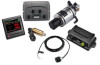
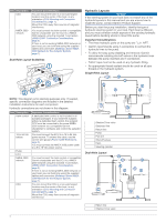
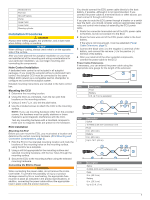
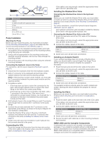
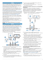
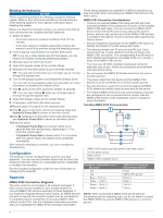
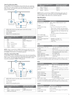
Item Description Splice 6 AWG (13.29 mm²) extension wire Fuse 8 in. (20.3 cm) Battery 8 in. (20.3 cm) Up to 36 ft. (11 m) Pump Installation Mounting the Pump Before you can mount the pump, you must select a location (Pump Mounting Considerations, page 2) and determine the correct mounting hardware (Tools Needed, page 1). 1 Hold the pump in the intended mounting location and mark the locations of the mounting holes on the mounting surface, using the pump as a template. 2 Using a drill bit appropriate for the mounting surface and selected mounting hardware, drill the four holes through the mounting surface. 3 Secure the pump to the mounting surface using the selected mounting hardware. Connecting the Hydraulic Lines to the Pump For assistance, see the layout diagrams (Hydraulic Layouts, page 4). 1 Disconnect the necessary lines from the hydraulic system. 2 Add a T-connector to the starboard and port lines of the system between the helm and the steering cylinder. NOTE: If the boat has a power-assist module, you must add the T-connectors between the power-assist module and the steering cylinder. 3 Complete an action: • If the boat does not have a return line connected to the helm, add enough hydraulic hose to connect the return fitting on the helm to the center pump fitting. • If the boat has a return line connected to the helm, add a T-connector to the return line. If the return line is connected to a power-assist module, you must add the Tconnector to the return line between the power-assist module and the helm. 4 Add hydraulic hose to the unused fitting on each T-connector, with enough hose to connect the T-connector to the pump fittings. 5 Connect the port and starboard line T-connectors to the appropriate pump fittings, as shown in the layout diagram for your hydraulic configuration. 6 Install the Shadow Drive valve in the port or starboard hydraulic line between the helm and the T-connector that connects to the pump (Installing the Shadow Drive Valve, page 6). 7 Install a shut-off valve (not included) on each hydraulic line that connects directly to the pump. Connecting the CCU Route the orange and blue wires from the bare-wire portion of the CCU cable to the location where you plan to install the alarm (Installing the Alarm, page 6). If the cable is not long enough, extend the appropriate wires with 0.08 mm2 (28 AWG) wire. Installing the Shadow Drive Valve Connecting the Shadow Drive Valve to the Hydraulic System Before you can install the Shadow Drive valve, you must select a location at which to connect the Shadow Drive to the hydraulic steering of your boat (Shadow Drive Mounting Considerations, page 2). For further assistance, consult the hydraulic-layout diagrams (Hydraulic Layouts, page 4). Use hydraulic connectors (not included) to install the Shadow Drive valve in the appropriate hydraulic line. Connecting the Shadow Drive Valve to the CCU 1 Route the bare-wire end of the CCU cable to the Shadow Drive valve. If the cable is not long enough, extend the appropriate wires with 28 AWG (0.08 mm²) wire. 2 Connect the cables, based on this table. Shadow Drive Valve Wire Color Red (+) Black (-) CCU Cable Wire Color Brown (+) Black (-) 3 Solder and cover all bare-wire connections. Installing an Autopilot Switch If your autopilot package does not include a Shadow Drive valve, you should install a manual Single Pole Single Throw (SPST) switch (not included) to disable the autopilot if necessary. 1 Route the bare-wire end of the CCU cable to the switch. If the cable is not long enough, extend the appropriate wires with 28 AWG (0.08 mm²) wire. 2 Connect the cables, based on this table. Switch Wire Function Positive (+) Negative (-) CCU Cable Wire Color Brown (+) Black (-) 3 Solder and cover all bare-wire connections. The autopilot functions correctly when the switch contacts are closed. Opening the switch disables the autopilot for manual steering. Installing the Alarm Before you can mount the alarm, you must select a mounting location (Alarm Mounting and Connection Considerations, page 2). 1 Route the alarm cable to the bare-wire end of the CCU cable. If the cable is not long enough, extend the appropriate wires with 28 AWG (0.08 mm2) wire. 2 Connect the cables, based on this table. Alarm Wire Color White (+) Black (-) CCU Cable Wire Color Orange (+) Blue (-) 3 Solder and cover all bare-wire connections. 4 Secure the alarm with cable ties or other mounting hardware (not included). NMEA 2000 and the Autopilot Components A dedicated helm control is not included in all autopilot packages. If you install the autopilot without a dedicated helm control, the autopilot CCU must be connected to the same NMEA 2000 network as a compatible Garmin chartplotter to configure and control the autopilot system. 6
-
 1
1 -
 2
2 -
 3
3 -
 4
4 -
 5
5 -
 6
6 -
 7
7 -
 8
8 -
 9
9 -
 10
10 -
 11
11 -
 12
12
 |
 |
