Garmin Compact Reactor 40 Hydraulic Autopilot with GHC 20 and Shadow Drive Pack - Page 2
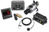
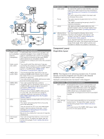
Power and Data Layout
 |
View all Garmin Compact Reactor 40 Hydraulic Autopilot with GHC 20 and Shadow Drive Pack manuals
Add to My Manuals
Save this manual to your list of manuals |
Page 2 highlights
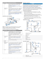
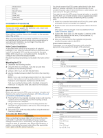
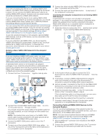
2 Locate the center of rotation of the boat, and measure the distance between the center of rotation and each of the suitable mounting locations you listed in step 1. 3 Select the location closest to the center of rotation. If more than one location is approximately the same distance from the center of rotation, you should select the location that best meets these considerations. • The best location is closest to the centerline of the boat. • The best location is lower in the boat. • The best location is slightly forward in the boat. Testing a Location for Magnetic Interference You can use a handheld compass to test a mounting location for magnetic interference. 1 Hold a handheld compass in the CCU mounting location. 2 Move the compass six inches to the left of the location, then six inches to the right, observe the needle, and select an action: • If the compass needle moves more than three degrees during this step, magnetic interference is present. Select a new mounting location and repeat the test. • If the compass needle does not move, or moves less than three degrees, proceed to the next step. 3 Repeat this process while moving the compass above and below the mounting location. 4 Repeat this process while moving the compass in front of and behind the mounting location. ECU Mounting and Connection Considerations • The ECU can be mounted on a flat surface, facing any direction. • Mounting screws are included with the ECU, but you may need to provide different screws if the supplied screws are not suitable for the mounting surface. • The ECU must be mounted within 0.5 m (19 in.) of the pump. ◦ The cables connecting the ECU to the pump cannot be extended. • The ECU must be mounted in a location where it will not be submerged or exposed to wash down. • The ECU power cable connects to the boat battery, and it can be extended if needed (Power Cable Extensions, page 5). Pump Mounting Considerations Consult the hydraulic-layout diagrams in these instructions to help determine the pump-installation location (Hydraulic Layouts, page 4). • The pump must be mounted at a location to which you can extend the hydraulic steering lines of the boat. • The pump should be mounted horizontally if possible. • If the pump must be mounted vertically, with the hydraulic connections facing upward. Shadow Drive Mounting Considerations NOTE: The Shadow Drive is a sensor you install in the hydraulic steering lines of your boat. It detects when you manually take control of the helm and suspends autopilot control of the boat. NOTE: If your autopilot package does not include a Shadow Drive, you should install a manual switch to disable the autopilot if needed. • The Shadow Drive must be mounted horizontally and as level as possible, with cable ties firmly securing it in place. • The Shadow Drive must be mounted at least 305 mm (12 in.) away from magnetic materials or devices, such as speakers or electric motors. • The Shadow Drive should be mounted closer to the helm than to the pump. • The Shadow Drive should be mounted lower than the lowest helm, but higher than the pump. • The Shadow Drive must not be connected directly to the fitting at the back of the helm. There must be a length of hose between the fitting at the helm and the Shadow Drive. • The Shadow Drive must not be connected directly to a hydraulic T-connector in the hydraulic line. There must be a length of hose between a T-connector and the Shadow Drive. • In a single-helm installation, there must not be a T-connector between the helm and the Shadow Drive. • In a dual-helm installation, the Shadow Drive should be installed between the pump and the hydraulic T-connector that leads to the upper and lower helm, closer to the Tconnector than to the pump. • The Shadow Drive must be installed in either the starboard steering line or the port steering line. The Shadow Drive must not be installed in either the return line or the high-pressure line, if applicable. Autopilot Switch Mounting and Connection Considerations If your autopilot package does not include a Shadow Drive valve, you should install a manual Single Pole Single Throw (SPST) switch (not included) to disable the autopilot if necessary. The switch should be installed near the primary helm, so it is easily accessible when operating the boat. The switch should be connected to the same wires that connect a Shadow Drive valve. If needed, the wires can be extended with 28 AWG (0.08 mm2) wire. Alarm Mounting and Connection Considerations • The alarm should be mounted near the primary helm station. • The alarm can be mounted under the dashboard. • If needed, the alarm wires can be extended with 28 AWG (0.08 mm2) wire. NMEA 2000® Connection Considerations • The CCU and the helm control must connect to a NMEA 2000 network. • If your boat does not already have a NMEA 2000 network, one can be built using the included NMEA 2000 cables and connectors (Building a Basic NMEA 2000 Network for the Autopilot System, page 7). • To use the advanced features of the autopilot, optional NMEA 2000 devices, such as a wind sensor, a water-speed sensor, or a GPS device, can be connected to the NMEA 2000 network. Power and Data Layout WARNING When connecting the power cable, do not remove the in-line fuse holder. To prevent the possibility of injury or product damage caused by fire or overheating, the appropriate fuse must be in place as indicated in the product specifications. In addition, connecting the power cable without the appropriate fuse in place voids the product warranty. 2
-
 1
1 -
 2
2 -
 3
3 -
 4
4 -
 5
5 -
 6
6 -
 7
7 -
 8
8 -
9
-
10
-
11
-
12
 |
 |
