Garmin Cortex VHF and AIS Cortex Hub Installation Guide - Page 8
Cortex Hub positioning, Cortex Hub mounting
 |
View all Garmin Cortex VHF and AIS manuals
Add to My Manuals
Save this manual to your list of manuals |
Page 8 highlights
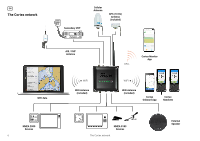
EN Cortex Hub positioning Allow at least 2"/ 50mm from each set of connectors give sufficient room for cable clearance and connection. Allow at least 8" / 200mm for the external WiFi antenna to be positioned in a vertical position to increase WiFi range. For optimal Heading Sensor performance, do not mount on or near ferrous materials. For configuration, see Heading Sensor on page 25 Ensure that the minimum safe compass distance is maintained. Standard: 0.8 m, Steering: 0.4 m. Cables Allow 2"/50mm WiFi Antenna Allow 8"/200mm Cortex Hub mounting 1. Use the Cortex Hub as a template for mounting holes 2. Mark the holes on the mounting surface and drill them 3. Align the Cortex Hub to the mounting holes and secure with fastenings of your choice (not included). Recommended screws: 316 Stainless Self Tapping 8G/1" (4.2/25.4mm) or 10G/1" (4.8/25.4mm) Pan/Round Head. The Cortex Hub features metal anti-compression rings in each mounting hole to prevent damage and ensure the Cortex Hub can be mounted securely. Cables Allow 2"/50mm 8 Cortex Hub positioning
-
 1
1 -
2
-
 3
3 -
 4
4 -
 5
5 -
 6
6 -
 7
7 -
 8
8 -
 9
9 -
 10
10 -
 11
11 -
 12
12 -
 13
13 -
14
-
15
-
16
-
17
-
18
-
19
-
20
-
21
-
22
-
23
-
24
-
25
-
26
-
27
-
28
-
29
-
30
-
31
-
32
-
33
-
34
-
35
-
36
-
37
-
38
-
39
-
40
-
41
-
42
 |
 |
