Garmin GDL 52 Installation Manual - Page 20
Installation Procedure, 3.1 Unpacking Unit, 3.2 Wiring Harness Installation, CAUTION
 |
View all Garmin GDL 52 manuals
Add to My Manuals
Save this manual to your list of manuals |
Page 20 highlights
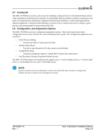
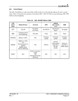
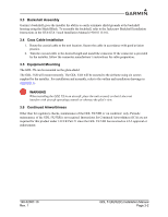
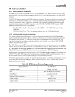
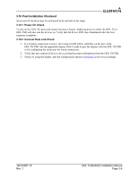
3 INSTALLATION PROCEDURE 3.1 Unpacking Unit Carefully unpack the equipment and make a visual inspection of the unit for evidence of damage incurred during shipment. If the unit is damaged, notify the carrier and file a claim. To justify a claim, save the original shipping container and all packing materials. Do not return the unit to Garmin until the carrier has authorized the claim. Retain the original shipping containers for storage. If the original containers are not available, a separate cardboard container should be prepared which is large enough to accommodate sufficient packing material to prevent movement. 3.2 Wiring Harness Installation Allow adequate space for installation of cables and connectors. The installer shall supply and fabricate all cables. All electrical connections to the GDL 51R/52R are made through one 15-pin D-subminiature connector. Section 4 defines the electrical characteristics of all input and output signals. Required connectors and associated hardware are supplied with the connector kit. See Appendix B for examples of interconnect wiring diagrams. Construct the actual harnesses in accordance with the aircraft manufacturer authorized interconnect standards. CAUTION Check wiring connections for errors before installing the GDL 51R/52R. Incorrect wiring could cause internal component damage. Table 3-1. Pin Contact Part Numbers Manufacturer [1] 15-pin D-Subminiature 20-24 AWG Garmin P/N 336-00022-02 Military P/N M39029/63-368 [1] Non-Garmin part numbers shown are not maintained by Garmin and consequently are subject to change without notice Table 3-2 Recommended Crimp Tools Manufacturer [1] Hand Crimping Tool 20-24 AWG Positioner Insertion/ Extraction Tool Military P/N M22520/2-01 M22520/2-08 M81969/1-04 Daniels N/A K13-1 M81969/1-04 [1] Non-Garmin part numbers shown are not maintained by Garmin and consequently are subject to change without notice. 190-02087-10 Rev. 1 GDL 51(R)/52(R) Installation Manual Page 3-1
-
 1
1 -
2
-
3
-
4
-
5
-
6
-
7
-
8
-
9
-
10
-
11
-
12
-
13
-
14
-
 15
15 -
 16
16 -
 17
17 -
 18
18 -
 19
19 -
 20
20 -
 21
21 -
 22
22 -
 23
23 -
 24
24 -
 25
25 -
26
-
27
-
28
-
29
-
30
-
31
-
32
-
33
-
34
-
35
-
36
-
37
 |
 |
