Garmin GDL 52 Installation Manual - Page 27
GDL 51/52 RS-232 Electrical Characteristics, GPS Antenna Connection, Table 4-2
 |
View all Garmin GDL 52 manuals
Add to My Manuals
Save this manual to your list of manuals |
Page 27 highlights
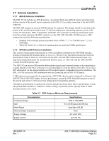
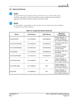
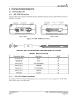
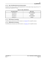
4.1.1.2 GDL 51/52 RS-232 Electrical Characteristics The RS-232 input/outputs conform to EIA Standard RS-232C with an output voltage swing of at least ± 5V when driving a standard RS-232 load. Table 4-2 GDL 51/52 RS-232 Connection Name RS-232 RX 2 RS-232 TX 2 RS-232 RX 1 RS-232 TX 1 Wire Color WHITE/ORANGE ORANGE WHITE/GREEN GREEN 4.1.1.3 GPS Antenna Connection The GPS antenna connection uses a MCX connector, see Section 3.9 for compatible antennas. 4.1.1.4 SXM Antenna Connection The SXM antenna connection uses a MCX connector, see Section 3.9 for compatible antennas. 190-02087-10 Rev. 1 GDL 51(R)/52(R) Installation Manual Page 4-2
-
 1
1 -
2
-
3
-
4
-
5
-
6
-
7
-
8
-
9
-
10
-
11
-
12
-
13
-
14
-
15
-
16
-
17
-
18
-
19
-
20
-
21
-
 22
22 -
 23
23 -
 24
24 -
 25
25 -
 26
26 -
 27
27 -
 28
28 -
 29
29 -
 30
30 -
 31
31 -
 32
32 -
33
-
34
-
35
-
36
-
37
 |
 |

190-02087-10
GDL 51(R)/52(R) Installation Manual
Rev. 1
Page 4-2
4.1.1.2
GDL 51/52 RS-232 Electrical Characteristics
The RS-232 input/outputs conform to EIA Standard RS-232C with an output voltage swing of at least ± 5V
when driving a standard RS-232 load.
4.1.1.3
GPS Antenna Connection
The GPS antenna connection uses a MCX connector, see
Section 3.9
for compatible antennas.
4.1.1.4
SXM Antenna Connection
The SXM antenna connection uses a MCX connector, see
Section 3.9
for compatible antennas.
Table 4-2
GDL 51/52 RS-232
Connection Name
Wire Color
RS-232 RX 2
WHITE/ORANGE
RS-232 TX 2
ORANGE
RS-232 RX 1
WHITE/GREEN
RS-232 TX 1
GREEN