Garmin GDL 52 Installation Manual - Page 21
Backshell Assembly, 3.4 Coax Cable Installation, 3.5 Equipment Mounting
 |
View all Garmin GDL 52 manuals
Add to My Manuals
Save this manual to your list of manuals |
Page 21 highlights
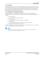
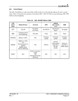
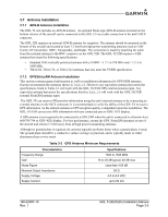
3.3 Backshell Assembly Garmin's backshell gives the installer the ability to easily terminate shield grounds at the backshell housing using the Shield Block. To assemble the backshell, refer to the Jackscrew Backshell Installation Instructions in the G3X/G3X Touch Installation Manual (190-01115-01). 3.4 Coax Cable Installation 1. Route the coaxial cable to the unit location. Secure the cable in accordance with good aviation practice. 2. Trim the coaxial cable to the desired length and install the connector. If the connector is provided by the installer, follow the connector manufacturer's instructions for cable preparation. 3.5 Equipment Mounting The GDL 5X can be mounted on the glare-shield. The GDL 5XR will mount remotely. The GDL 5XR will be secured to the airframe using six screws supplied by the installer. For installation and assembly, refer to the outline and installation drawings in Appendix A. WARNING When installing the GDL 5X in an aircraft, place the unit securely so that it does not interfere with aircraft operating controls or obstruct the pilot's view. 3.6 Continued Airworthiness Other than for regulatory checks, maintenance of the GDL 5X/5XR is 'on condition' only. Periodic maintenance of the GDL 5X/5XR is not required. Instructions for Continued Airworthiness (ICA) are not required for this product under 14 CFR Part 21 since the GDL 5X/5XR has received no FAA approval or endorsement. 190-02087-10 Rev. 1 GDL 51(R)/52(R) Installation Manual Page 3-2
-
 1
1 -
2
-
3
-
4
-
5
-
6
-
7
-
8
-
9
-
10
-
11
-
12
-
13
-
14
-
15
-
 16
16 -
 17
17 -
 18
18 -
 19
19 -
 20
20 -
 21
21 -
 22
22 -
 23
23 -
 24
24 -
 25
25 -
 26
26 -
27
-
28
-
29
-
30
-
31
-
32
-
33
-
34
-
35
-
36
-
37
 |
 |
