GE DPVH880EJWW Owners Manual - Page 18
Installation Instructions, CONNECTING A GAS DRYER cont.
 |
UPC - 084691169840
View all GE DPVH880EJWW manuals
Add to My Manuals
Save this manual to your list of manuals |
Page 18 highlights
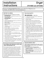
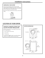
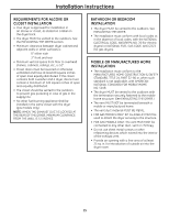
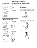
Installation Instructions CONNECTING A GAS DRYER (cont.) CONNECTING THE DRYER TO THE GAS SUPPLY A Install a female 3/8″ NPT elbow at the end of the dryer gas inlet. Install a 3/8″ flare union adapter to the female elbow. IMPORTANT: Use a pipe wrench to securely hold on to the end of the dryer gas inlet to prevent twisting the inlet. NOTE: Apply pipe compound or Teflon® tape to the threads of the adapter and dryer gas inlet. CONNECTING THE DRYER TO THE GAS SUPPLY (cont.) D Install a 1/8″ NPT plugged tapping to the dryer gas line shut-off valve for checking gas inlet pressure. Install a flare union adapter to the plugged tapping. NOTE: Apply pipe compound or Teflon® tape to the threads of the adapter and plugged tapping. New Metal Flexible Gas Line Connector Adapter Elbow Items not supplied 3/8″ NPT Adapter 1/8″ NPT Pipe Plug for Checking Gas Inlet Pressure Shut-Off Valve Pipe size at least 1/2″ B Attach the flexible metal gas line connector to the adapter. Apply pipe compound or Teflon® tape to all male threads. Plugged Tapping Shut-off Valve E Tighten all connections, using two adjustable wrenches. Do not overtighten. Apply pipe compound to the adapter and dryer gas inlet. C Tighten the flexible gas line connection, using two adjustable wrenches. F Open the gas shutoff valve. 18
-
 1
1 -
2
-
3
-
4
-
5
-
6
-
7
-
8
-
9
-
10
-
11
-
12
-
 13
13 -
 14
14 -
 15
15 -
 16
16 -
 17
17 -
 18
18 -
 19
19 -
 20
20 -
 21
21 -
 22
22 -
 23
23 -
24
-
25
-
26
-
27
-
28
-
29
-
30
-
31
-
32
-
33
-
34
-
35
-
36
-
37
-
38
-
39
-
40
-
41
-
42
-
43
-
44
-
45
-
46
-
47
-
48
-
49
-
50
-
51
-
52
-
53
-
54
-
55
-
56
-
57
-
58
-
59
-
60
-
61
-
62
-
63
-
64
-
65
-
66
-
67
-
68
-
69
-
70
-
71
-
72
-
73
-
74
-
75
-
76
-
77
-
78
-
79
-
80
-
81
-
82
-
83
-
84
-
85
-
86
-
87
-
88
-
89
-
90
-
91
-
92
-
93
-
94
-
95
-
96
-
97
-
98
-
99
-
100
-
101
-
102
-
103
-
104
-
105
-
106
-
107
-
108
-
109
-
110
-
111
-
112
-
113
-
114
-
115
-
116
-
117
-
118
-
119
-
120
-
121
-
122
-
123
-
124
-
125
-
126
-
127
-
128
-
129
-
130
-
131
-
132
-
133
-
134
-
135
-
136
-
137
-
138
-
139
-
140
-
141
-
142
-
143
-
144
-
145
-
146
-
147
-
148
-
149
-
150
-
151
-
152
 |
 |
