GE DPVH880EJWW Owners Manual - Page 28
WARNING, EXHAUSTING THE DRYER cont., Installation Instructions
 |
UPC - 084691169840
View all GE DPVH880EJWW manuals
Add to My Manuals
Save this manual to your list of manuals |
Page 28 highlights
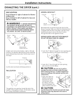
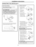
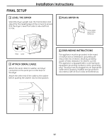
Installation Instructions EXHAUSTING THE DRYER (cont.) SIDE VENTING: Dryer Exhaust to right of cabinet for Electric models only. Dryer Exhaust to left of cabinet for Gas and Electric models. ADDING A NEW DUCT Fixing hole Portion "A" WARNING - BEFORE PERFORMING THIS EXHAUST INSTALLATION, BE SURE TO DISCONNECT THE DRYER FROM ITS ELECTRICAL SUPPLY. PROTECT YOUR HANDS AND ARMS FROM SHARP EDGES WHEN WORKING INSIDE THE CABINET. BE SURE TO WEAR GLOVES. Remove Right screw and save Left side exhaust Reconnect the cut portion (A) of the duct to the blower housing. Make sure that the shortened duct is aligned with the tab in the base. Use the screw saved previously to secure the duct in place through the tab on the appliance base. ADDING ELBOW AND DUCT FOR EXHAUST TO LEFT OR RIGHT SIDE OF CABINET Internal duct Left Bottom Remove desired knockout (one only) Detach and remove the bottom, right or left side knockout as desired. Remove the screw inside the dryer exhaust duct and save. Pull the duct out of the dryer. Fixing hole A Rear opening • Insert the 4″ elbow through the rear opening and connect the elbow to the dryer internal duct. Side opening 133⁄8″ Cut the duct as shown and keep portion A. TAB LOCATION Not for gas • Insert the 4″ duct through the side opening and connect it to the elbow. CAUTION: Be sure not to pull or damage the electrical wires inside the dryer when inserting the duct. A slight interference may occur between the exhaust and the wire components. Bend tab up 45° • Apply duct tape as shown on the joint Duct tape between the dryer internal duct and the elbow, and also the joint between the elbow and the side duct. Through the rear opening, locate the tab in the CAUTION: middle of the appliance base. Lift the tab to about Internal duct joints must be secured with tape; 45°, using a flat blade screwdriver. otherwise, they may separate and cause a safety hazard. 28
-
 1
1 -
2
-
3
-
4
-
5
-
6
-
7
-
8
-
9
-
10
-
11
-
12
-
13
-
14
-
15
-
16
-
17
-
18
-
19
-
20
-
21
-
22
-
 23
23 -
 24
24 -
 25
25 -
 26
26 -
 27
27 -
 28
28 -
 29
29 -
 30
30 -
 31
31 -
 32
32 -
 33
33 -
34
-
35
-
36
-
37
-
38
-
39
-
40
-
41
-
42
-
43
-
44
-
45
-
46
-
47
-
48
-
49
-
50
-
51
-
52
-
53
-
54
-
55
-
56
-
57
-
58
-
59
-
60
-
61
-
62
-
63
-
64
-
65
-
66
-
67
-
68
-
69
-
70
-
71
-
72
-
73
-
74
-
75
-
76
-
77
-
78
-
79
-
80
-
81
-
82
-
83
-
84
-
85
-
86
-
87
-
88
-
89
-
90
-
91
-
92
-
93
-
94
-
95
-
96
-
97
-
98
-
99
-
100
-
101
-
102
-
103
-
104
-
105
-
106
-
107
-
108
-
109
-
110
-
111
-
112
-
113
-
114
-
115
-
116
-
117
-
118
-
119
-
120
-
121
-
122
-
123
-
124
-
125
-
126
-
127
-
128
-
129
-
130
-
131
-
132
-
133
-
134
-
135
-
136
-
137
-
138
-
139
-
140
-
141
-
142
-
143
-
144
-
145
-
146
-
147
-
148
-
149
-
150
-
151
-
152
 |
 |
