GE GUD27GSSJWW Installation Instructions - Page 9
Warning, Warning, Warning
 |
View all GE GUD27GSSJWW manuals
Add to My Manuals
Save this manual to your list of manuals |
Page 9 highlights
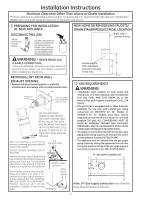
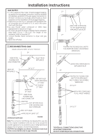
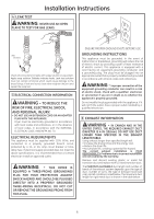
Installation Instructions DO ELBOW HIGHLY RECOMMENDED EXHAUST TO LEFT OR RIGHT SIDE OF CABINET • For side ducting, remove the knockout (ONLY 1). Rotate elbow sections so that the opening points to the side. Preassemble 4" elbow with 4" duct. Use only 4" UL approved rigid metal for ducting inside the dryer. • Insert duct assembly through the side opening and connect to the internal elbow. - WARNING Be sure not to pull or damage the electrical wires inside the dryer when inserting the duct . 4" UL approved rigid metal DO NOT USE EXCESSIVE EXHAUST LENGTH DON'T DO NOT SIT APPLIANCE ON FLEXIBLE EXHAUST DO NOT CRUSH FLEXIBLE EXHAUST AGAINST WALL 9 24" MODELS ONLY: DRYER EXHAUST TO RIGHT, LEFT OR BOTTOM CABINET WARNING - BEFORE PERFORMING THIS EXHAUST INSTALLATION, BE SURE TO DISCONNECT THE APPLIANCE FROM ITS ELECTRICAL SUPPLY. PROTECT YOUR HANDS AND ARMS FROM SHARP EDGES WHEN WORKING INSIDE THE CABINET. BE SURE TO WEAR GLOVES. For downward venting, rotate elbow sections so that elbow points downward REMOVE DESIRED KNOCKOUT (ONLY 1) DUCT TAPE • Apply duct tape as shown on the joint between the dryer internal duct and the straight duct pipe. WARNING- Internal duct joints must be secured with tape, otherwise they may separate and cause a safety hazard. 27" MODELS ONLY: DRYER EXHAUST TO RIGHT, LEFT OR BOTTOM CABINET WARNING - BEFORE PERFORMING THIS EXHAUST INSTALLATION, BE SURE TO DISCONNECT THE APPLIANCE FROM ITS ELECTRICAL SUPPLY. PROTECT YOUR HANDS AND ARMS FROM SHARP EDGES WHEN WORKING INSIDE THE CABINET. BE SURE TO WEAR GLOVES. For downward venting, rotate elbow sectionsm, so that elbow points downward. FLOOR 9
-
 1
1 -
2
-
3
-
 4
4 -
 5
5 -
 6
6 -
 7
7 -
 8
8 -
 9
9 -
 10
10 -
 11
11 -
 12
12 -
 13
13 -
 14
14 -
15
-
16
-
17
-
18
-
19
-
20
-
21
-
22
-
23
-
24
-
25
-
26
-
27
-
28
-
29
-
30
-
31
-
32
-
33
-
34
-
35
-
36
 |
 |
