GE JVM1665SNSS Installation Instructions
GE JVM1665SNSS Manual
 |
UPC - 084691187387
View all GE JVM1665SNSS manuals
Add to My Manuals
Save this manual to your list of manuals |
GE JVM1665SNSS manual content summary:
- GE JVM1665SNSS | Installation Instructions - Page 1
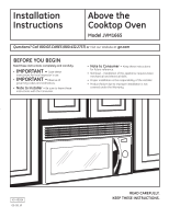
Installation Instructions Above the Cooktop Oven Model JVM1665 Questions? Call 800.GE.CARES (800.432.2737) or Visit our Website at: ge.com BEFORE YOU BEGIN Read these instructions completely and carefully. • IMPORTANT - Save these instructions for local inspector's use. • IMPORTANT -Observe all - GE JVM1665SNSS | Installation Instructions - Page 2
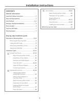
Installation Instructions CONTENTS General information Important Safety Instructions 3 Electrical Requirements 3 Hood Exhaust 4, 5 Damage-Shipment/Installation 6 Parts Included 6 Tools You Will Need 7 Mounting Space 7 Step-by-step installation guide Exhaust Adapter to Oven Rear Panel 15 - GE JVM1665SNSS | Installation Instructions - Page 3
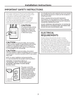
beginning installation to avoid severe or fatal shock injury. CAUTION: For personal safety, the mounting surface must be capable of supporting the cabinet above the oven. The outlet box and supply circuit should be installed by a qualified electrician and conform to the National Electrical Code or - GE JVM1665SNSS | Installation Instructions - Page 4
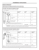
Installation Instructions HOOD EXHAUST NOTE: Read these next two pages only page 6. OUTSIDE TOP EXHAUST (EXAMPLE ONLY) The following chart describes an example of one possible ductwork installation. DUCT PIECES EQUIVALENT LENGTH x NUMBER USED EQUIVALENT = LENGTH Roof Cap 24 Ft. x (1) = - GE JVM1665SNSS | Installation Instructions - Page 5
Installation Instructions NOTE: If you need to install ducts, note that the total duct length of 31⁄4″ x 10″ HOOD EXHAUST DUCT. Read the following carefully. NOTE: It is important that venting be installed using the most direct route and with as few elbows as possible. This ensures clear - GE JVM1665SNSS | Installation Instructions - Page 6
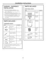
(plastic) 2 1 black 2 bronze 1 You will find the installation hardware contained in a packet with the unit. Check to make sure you have all these parts. NOTE: Some extra parts are included. Installation 1 Instructions Separately 1 Packed Grease Filter Exhaust 1 Adapter Damper 1 6 - GE JVM1665SNSS | Installation Instructions - Page 7
Kit may be used to fill in the gap between the oven and the cabinets. Your Owner's Manual contains the kit number for your model. • This oven is for installation over ranges up to 36″ wide. • If you are going to vent your oven to the outside, see Hood Exhaust Section for exhaust duct preparation - GE JVM1665SNSS | Installation Instructions - Page 8
FROM THE CARTON/REMOVING THE MOUNTING PLATE 1 Remove the turntable, installation instructions, filters, exhaust Adapter, damper, shelf and the small hardware bag. Do not remove the Styrofoam protecting the front of the oven. 2 Fold back all 4 carton flaps fully against carton sides. Then carefully - GE JVM1665SNSS | Installation Instructions - Page 9
Installation Instructions C. DETERMINING WALL PLATE LOCATION UNDER YOUR CABINET Plate position cabinets may have decorative trim that interferes with the oven installation. Remove the decorative trim to install the oven properly and to make it level. THE OVEN MUST BE LEVEL. Use a level to make sure - GE JVM1665SNSS | Installation Instructions - Page 10
Installation Instructions Hole D NOTE: Appearance and shape of the mounting plate may vary from your model. NOTE: Holes C and D are inside area E. If neither C nor D at least one wood screw mounted firmly in a stud to support the weight of the oven. Set the mounting plate aside. 4 Drill holes on the - GE JVM1665SNSS | Installation Instructions - Page 11
for non-vented exhaust, a disposable charcoal filter is included with the oven and needs to be installed to help remove smoke and odors. On models shipped for outside top exhaust, a Charcoal Filter Accessory Kit is required for the non-vented exhaust. (See your Owner's Manual for the kit number.) - GE JVM1665SNSS | Installation Instructions - Page 12
Installation Instructions A OUTSIDE TOP EXHAUST (Vertical Duct) INSTALLATION OVERVIEW A1. Attach Mounting Plate to Wall A2. Prepare Top Cabinet A3. Install Adapter A4. Mount Oven A5. Adjust Exhaust Adapter A6. Connect Ductwork A1. ATTACH THE MOUNTING PLATE TO THE WALL To use toggle bolts: - GE JVM1665SNSS | Installation Instructions - Page 13
Installation Instructions A2. USE TOP CABINET TEMPLATE FOR PREPARATION OF TOP CABINET You need to drill holes for the top support screws, a hole large enough for the power cord to fit through, and a cutout large enough for the exhaust adapter. A4. MOUNT THE OVEN • Read the instructions on the top - GE JVM1665SNSS | Installation Instructions - Page 14
House Duct 4 Tighten the three screws to the top of the oven completely. (While tightening screws, hold the oven in place against the wall and the top cabinet.) 5 Install grease filters. See the Owner's Manual packed with the oven. 1 Extend the house duct down to connect to the exhaust adapter - GE JVM1665SNSS | Installation Instructions - Page 15
for holes A and B in the wall plate. 3 Cut the opening, following the instructions of the REAR WALL TEMPLATE. Guide Guide Locking Tabs Push in securely until it is in the lower locking tabs. Take care to assure the damper hinge is installed so that it is at the top and that the damper swings - GE JVM1665SNSS | Installation Instructions - Page 16
Installation Instructions B3. ATTACH THE MOUNTING PLATE TO THE WALL B4. USE TOP CABINET TEMPLATE FOR PREPARATION OF TOP CABINET You need to drill holes for the top support screws and a hole large enough for the power cord to fit through. Attach the plate to the wall using toggle bolts. At least - GE JVM1665SNSS | Installation Instructions - Page 17
Installation Instructions B5. ADAPTING BLOWER FOR OUTSIDE BACK EXHAUST 1 Remove the two screws that hold the blower plate and remove the screw holding the blower motor to the oven. Slide blower plate from under its retaining flange. Retaining Flange Blower Plate 2 Carefully pull out the blower - GE JVM1665SNSS | Installation Instructions - Page 18
Installation Instructions B6. MOUNT THE OVEN FOR EASIER INSTALLATION AND PERSONAL SAFETY, WE RECOMMEND THAT TWO PEOPLE INSTALL THIS OVEN. IMPORTANT: Do not grip or use handle during installation. NOTE: If your cabinet is metal, use the nylon grommet around the power cord hole to prevent cutting of - GE JVM1665SNSS | Installation Instructions - Page 19
Installation Instructions C RECIRCULATING (Non-Vented Ductless) INSTALLATION OVERVIEW C1. Attach Mounting Plate to Wall C2. Prepare Top Cabinet C3. Adjust Blower C4. Mount the Oven C5. Install TOP CABINET You need to drill holes for the top support screws and a hole large enough for the power cord - GE JVM1665SNSS | Installation Instructions - Page 20
Installation Instructions C3. ADAPTING BLOWER FOR RECIRCULATION NOTE: The exhaust Adapter with damper is not needed for recirculating models. You may want to save them for possible future use. 1 Remove and save screws that hold blower plate and blower unit to the oven. Blower Plate Screws Blower - GE JVM1665SNSS | Installation Instructions - Page 21
Installation Instructions C3. ADAPTING BLOWER FOR RECIRCULATION (continued) 5 Place the blower unit back into the opening. CAUTION: Do not pull or stretch the blower unit wiring. Make sure the wires are not pinched. NOTE: When mounting the oven, thread power cord through hole in bottom of top - GE JVM1665SNSS | Installation Instructions - Page 22
Installation Instructions C4. MOUNT THE OVEN (continued) 3 Attach the oven to the top cabinet by inserting the filter into the top of the opening, between the side support slots. 5 Install grease filters. See the Owner's Manual packed with the oven. 5 Push the filter all the way in where it will - GE JVM1665SNSS | Installation Instructions - Page 23
the Owner's Manual. 2. Remove all packing material from the oven. 3. Install turntable and wheeled ring in cavity. 4. Replace house fuse or turn breaker back on. 7. KEEP INSTALLATION INSTRUCTIONS FOR THE LOCAL INSPECTOR'S USE. 5. Plug power cord into a dedicated 15 to 20 amp electrical outlet - GE JVM1665SNSS | Installation Instructions - Page 24
Printed in China - GE JVM1665SNSS | Installation Instructions - Page 25
Instrucciones de instalación Horno para colocar encima de la estufa Modelo JVM1665 ¿Preguntas? Llame 800-GE-CARES (800.432.2737) o visite nuestra página en la red en: ge.com ANTES DE EMPEZAR Lea estas instrucciones completa y cuidadosamente. • IMPORTANTE - Guarde estas instrucciones para el uso - GE JVM1665SNSS | Installation Instructions - Page 26
Instrucciones de instalación CONTENIDO Información general Instrucciones de seguridad importantes 3 Requisitos eléctricos 3 Campana de escape 4, 5 Daños - Envío / Instalación 6 Partes incluidas 6 Herramientas que necesitar 7 Espacio de montaje 7 C Recirculación 19-22 Cómo adherir el plato - GE JVM1665SNSS | Installation Instructions - Page 27
debe estar conectado a un circuito de suministro del voltaje y frecuencia apropiados. El tamaño del alambre debe conformarse a los requisitos del National Electric Code o al código local en efecto para este índice de kilovatios. El cable eléctrico de alimentación y el interruptor deberán llevarse - GE JVM1665SNSS | Installation Instructions - Page 28
12 pies 12 pies (redondo de 6″) x (1) = 12 pies Adaptador de transición 5 pies de rectángulo a redondo* x (1) = 5 pies La longitud de las partes de los conductos equivalentes está basada en pruebas reales y reflejan los requisitos para lograr una buena ventilación con cualquier campana de - GE JVM1665SNSS | Installation Instructions - Page 29
án ser cortadas para que encajen, usando las tijeras de corte, para permitir el movimiento libre del regulador de tiros. 5 La longitud de las partes de conductos equivalentes está basada en pruebas reales y reflejan los requisitos para lograr una buena ventilación con cualquier campana de escape. - GE JVM1665SNSS | Installation Instructions - Page 30
en un paquete junto con la unidad. Inspeccione para cerciorarse de que tiene todas las partes. NOTA: Se incluyen algunas partes adicionales. PARTES INCLUIDAS PARTES ADICIONALES PartE CANTIDAD Plantilla para 1 el gabinete superior Plantilla 1 para la pared posterior Instrucciones 1 de - GE JVM1665SNSS | Installation Instructions - Page 31
2″ 66″ o más desde el piso hasta la parte superior del horno NOTAS: El extremo del fondo del entre el horno y los gabinetes. min. Su Manual del Propietario contiene el número Protector posterior de del conducto de escape. • Cuando se instale el horno debajo de gabinetes de fondos lisos - GE JVM1665SNSS | Installation Instructions - Page 32
protege el frente del horno. 2 Pliegue hacia atrás las alas de la caja. Luego, cuidadosamente ruede el horno hasta que quede apoyado sobre la parte superior. El horno deberá descansar sobre la espuma de poliestireno. Caja Poliestireno 3 Tire de la caja hacia arriba y retírela del horno. 4 El plato - GE JVM1665SNSS | Installation Instructions - Page 33
para cerciorarse de que el fondo del gabinete está nivelado. Si los gabinetes tienen un saliente frontal solamente, sin marco posterior o lateral, instale el pla del saliente. Este mantendrá el horno nivelado. 1 Mida la profundidad interna del frente del saliente. 2 Trace una línea horizontal en - GE JVM1665SNSS | Installation Instructions - Page 34
Instrucciones de instalación D. CÓMO ALINEAR EL PLATO DE MONTAJE SOBRE LA PARED Agujero A Trace une línea vertical en la pared a partir del centro del gabinete superior Agujero B Agujero C PRECAUCIÓN: Use guantes de protección para evitar cortaduras en sus dedos con los extremos filosos. Area E - GE JVM1665SNSS | Installation Instructions - Page 35
. En los modelos despachados con escape superior exterior, se necesita un kit de accesorios de filtro de carbonilla para el sistema sin ventilación. (Consulte el Manual del propietario para obtener el número del kit.) 11 - GE JVM1665SNSS | Installation Instructions - Page 36
PERSPECTIVA GENERAL DE LA INSTALACIÓN A1. Como adherir el plato de montaje a la pared A2. Prepare el gabinete superior A3. Instale el del gabinete. PRECAUCIÓN: Tenga cuidado de evitar pellizcar sus dedos entre la parte posterior del plato de montaje y la pared. 4 Apriete todos los tornillos - GE JVM1665SNSS | Installation Instructions - Page 37
cuando perfore los agujeros en el fondo del gabinete. A3. ENSAMBLAJE E INSTALACIÓN DEL ADAPTADOR Regulador de tiro Adaptador de escape Plato del calefactor Parte posterior del horno NOTA: En algunos modelos, es posible que el adaptador de escape y la unidad del regulador de tiro ya estén colocados - GE JVM1665SNSS | Installation Instructions - Page 38
de arriba del horno. (Mientras aprieta los tornillos, mantenga el horno en su lugar contra la parte y el gabinete superior). 5 Instale los filtros de grasa. Ver el Manual del Propietario que viene con el horno. 1 Extienda el conducto de la casa hacia abajo para conectarlo con el adaptador de escape - GE JVM1665SNSS | Installation Instructions - Page 39
B ESCAPE POSTERIOR EXTERNO (Conducto horizontal) PERSPECTIVA GENERAL DE LA INSTALACIÓN B1. Prepare la pared posterior POSTERIOR DEL HORNO 1 Desatornille y retire la unidad del adaptador de escape de la parte superior del horno. Adaptador de escape 2 Fije el adaptador de escape al panel posterior del - GE JVM1665SNSS | Installation Instructions - Page 40
contra la pared y de que el plato esté centrado apropiadamente debajo del gabinete. PRECAUCIÓN: Tenga cuidado de evitar pellizcar sus dedos entre la parte posterior del plato de montaje y la pared. 4 Apriete todos los tornillos. Tire del plato en dirección opuesta a la pared para ayudar a apretar - GE JVM1665SNSS | Installation Instructions - Page 41
de que los alambres no están pellizcados. NOTA: Las aberturas del escape del calefactor deberán encajar con las aberturas del escape en la parte posterior del horno. 6 Coloque el plato calefactor en la misma posición como estaba antes y reinstale los tornillos del plato calefactor y del motor del - GE JVM1665SNSS | Installation Instructions - Page 42
del retroceso del gabinete Tornillos autoalineables Parte superior del horno 3 Pegue el horno a la parte superior del gabinete insertando tres tornillos frente del horno contra el fondo del gabinete. 5 Instale los filtros de grasa. Ver el Manual del Propietario que viene con el horno. 18 - GE JVM1665SNSS | Installation Instructions - Page 43
GENERAL DE LA INSTALACIÓN C1. Pegue el plato de montaje a la pared C2. Prepare el gabinete superior C3. Ajuste el calefactor C4. Monte el horno C5. Instale gabinete. PRECAUCIÓN: Tenga cuidado de evitar pellizcar sus dedos entre la parte posterior del plato de montaje y la pared. 4 Apriete todos los - GE JVM1665SNSS | Installation Instructions - Page 44
los tornillos que sostienen el plato del calefactor y la unidad del calefactor en el horno. Tornillos del plato del calefactor Plato del calefactor Parte posterior del horno Tornillo del motor del calefactor 2 Deslice el plato calefactor por debajo de su reborde de retención y remueva el. 4 Ruede - GE JVM1665SNSS | Installation Instructions - Page 45
plato del calefactor y los tornillos del plato del calefactor y del motor retirados en el Paso 1. Tornillos del plato calefactor Plato del calefactor Parte posterior del horno Tornillo del motor del calefactor C4. MONTAJE DEL HORNO 2 Gire el frente del horno contra el fondo del gabinete. Frente - GE JVM1665SNSS | Installation Instructions - Page 46
aprieta los tornillos, mantenga el horno en su lugar contra la pared y el gabinete superior.) 5 Instale los filtros de grasa. Ver el Manual del Propietario que viene con el horno. 4 Inserte la parte superior del filtro hacia arriba y en las ranuras al interior de la abertura superior. 5 Empuje el - GE JVM1665SNSS | Installation Instructions - Page 47
instrucciones. 5. Enchufe el cable eléctrico en un tomacorriente exclusivo de 15 a 20 amperios. 2. Remueva todos los materiales de embalaje del horno. 3. Instale el aro rotatorio y con ruedas en la cavidad. 4. Reemplace el fusible de la casa o encienda de nuevo el interruptor. Cerciórese de - GE JVM1665SNSS | Installation Instructions - Page 48
Impreso en China
-
 1
1 -
 2
2 -
 3
3 -
 4
4 -
 5
5 -
 6
6 -
 7
7 -
8
-
9
-
10
-
11
-
12
-
13
-
14
-
15
-
16
-
17
-
18
-
19
-
20
-
21
-
22
-
23
-
24
-
25
-
26
-
27
-
28
-
29
-
30
-
31
-
32
-
33
-
34
-
35
-
36
-
37
-
38
-
39
-
40
-
41
-
42
-
43
-
44
-
45
-
46
-
47
-
48
 |
 |
Questions? Call 800.GE.CARES (800.432.2737)
or
Visit our Website at:
ge.com
READ CAREFULLY.
KEEP THESE INSTRUCTIONS.
Installation
Above the
Instructions
Cooktop Oven
Model JVM1665
Read these instructions completely and carefully.
•
IMPORTANT –
Save these
instructions for local inspector’s use.
•
IMPORTANT –
Observe all
governing codes and ordinances.
•
Note to Installer
–
Be sure to leave these
instructions with the Consumer.
BEFORE YOU BEGIN
•
Note to Consumer –
Keep these instructions
for future reference.
•
Skill level – Installation of this appliance requires basic
mechanical and electrical skills.
•
Proper installation is the responsibility of the installer.
•
Product failure due to improper installation is not
covered under the Warranty.
49-40584
06-08 JR