Gigabyte GA-X48-DS4 Manual
Gigabyte GA-X48-DS4 Manual
 |
UPC - 818313005625
View all Gigabyte GA-X48-DS4 manuals
Add to My Manuals
Save this manual to your list of manuals |
Gigabyte GA-X48-DS4 manual content summary:
- Gigabyte GA-X48-DS4 | Manual - Page 1
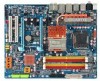
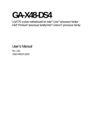
GA-X48-DS4 LGA775 socket motherboard for Intel® CoreTM processor family/ Intel® Pentium® processor family/Intel® Celeron® processor family User's Manual Rev. 1301 12ME-X48DS4-1301R - Gigabyte GA-X48-DS4 | Manual - Page 2
Motherboard GA-X48-DS4 Apr. 4, 2008 Motherboard GA-X48-DS4 Apr. 4, 2008 - Gigabyte GA-X48-DS4 | Manual - Page 3
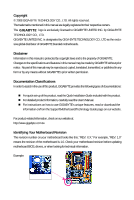
with the product. „ For detailed product information, carefully read the User's Manual. „ For instructions on how to use GIGABYTE's unique features, read or download the information on/from the Support\Motherboard\Technology Guide page on our website. For product-related information, check on our - Gigabyte GA-X48-DS4 | Manual - Page 4
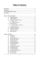
Box Contents ...6 OptionalItems ...6 GA-X48-DS4 Motherboard Layout 7 Block Diagram ...8 Chapter 1 Hardware Installation 9 1-1 Installation Precautions 9 1-2 Product Specifications 10 1-3 Installing the CPU and CPU Cooler 13 1-3-1 Installing the CPU 13 1-3-2 Installing the CPU Cooler 15 - Gigabyte GA-X48-DS4 | Manual - Page 5
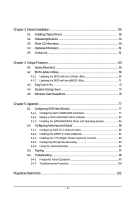
68 4-2-2 Updating the BIOS with the @BIOS Utility 71 4-3 EasyTune 5 Pro 73 4-4 Dynamic Energy Saver 74 4-5 Windows Vista ReadyBoost 76 Chapter 5 Appendix ...77 5-1 Configuring SATA Hard Drive(s 77 5-1-1 Configuring Intel® ICH9R SATA Controllers 77 5-1-2 Making a SATA RAID/AHCI Driver Diskette - Gigabyte GA-X48-DS4 | Manual - Page 6
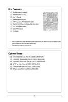
Box Contents GA-X48-DS4 motherboard Motherboard driver disk User's Manual Quick Installation Guide Intel® LGA775 CPU Installation Guide One IDE cable and one floppy disk drive cable Four SATA 3Gb/s cables One SATA bracket I/O Shield • The box contents above are for reference only - Gigabyte GA-X48-DS4 | Manual - Page 7
GA-X48-DS4 Motherboard Layout KB_MS RCA_SPDIF USB_1394_1 SYS_FAN1 ATX_12V_2X LGA775 CPU_FAN PHASE LED ATX USB_1394_2 USB_LAN1 USB_LAN2 AUDIO RTL8111C F_AUDIO PCIE_1 NB_FAN RTL8111C CODEC CD_IN PCIE_16_1 PCIE_2 PCIE_3 BP_BIOS MAIN_BIOS PCIE_16_2 Intel® X48 GA-X48-DS4 BAT CLR_CMOS - Gigabyte GA-X48-DS4 | Manual - Page 8
Express x16 LGA775 Processor CPU CLK+/(400/333/266/200 MHz) Host Interface DDR2 1200/1066/800/667 MHz LAN2 LAN1 3 PCI Express x1 PCIe CLK (100 MHz) RJ45 RTL 8111C RJ45 RTL 8111C x1 x1 x1 x1 x1 PCI Express Bus ATA-133/100/66/ 33 IDE Channel GIGABYTE SATA2 Intel® X48 Intel® ICH9R Dual - Gigabyte GA-X48-DS4 | Manual - Page 9
manual and follow these procedures: • Prior to installation, do not remove or break motherboard S/N (ESD) wrist strap when handling electronic components such as a motherboard, CPU or memory. If you do not have an ESD wrist steps or have a problem related to the use of the product, please consult - Gigabyte GA-X48-DS4 | Manual - Page 10
® Celeron® processor in the LGA 775 package (Go to GIGABYTE's website for the latest CPU support list.) Š L2 cache varies with CPU Š 1600/1333/1066/800 MHz FSB Š North Bridge: Intel® X48 Express Chipset Š South Bridge: Intel® ICH9R Š 4 x 1.8V DDR2 DIMM sockets supporting up to 8 GB of system memory - Gigabyte GA-X48-DS4 | Manual - Page 11
Out/Microphone) I/O Controller Š iTE IT8718 chip Hardware Monitor Š System voltage detection Š CPU/System temperature detection Š CPU/System/Power fan speed detection Š CPU overheating warning Š CPU/System/Power fan fail warning Š CPU fan speed control (Note 2) - 11 - Hardware Installation - Gigabyte GA-X48-DS4 | Manual - Page 12
you install. (Note 3) Available functions in Easytune may differ by motherboard model. (Note 4) The adjustable CPU voltage range depends on the CPU being used. (Note 5) Due to chipset limitation, Intel ICH9R RAID driver does not support Windows 2000 operating system. GA-X48-DS4 Motherboard - 12 - - Gigabyte GA-X48-DS4 | Manual - Page 13
do so according to your hardware specifications including the CPU, graphics card, memory, hard drive, etc. 1-3-1 Installing the CPU A. Locate the alignment keys on the motherboard CPU socket and the notches on the CPU. LGA775 CPU Socket Alignment Key LGA 775 CPU Alignment Key Pin One Corner of the - Gigabyte GA-X48-DS4 | Manual - Page 14
pin one corner of the CPU socket (or you may align the CPU notches with the socket alignment keys) and gently insert the CPU into position. Step 5: Once the CPU is properly inserted, replace the load plate and push the CPU socket lever back into its locked position. GA-X48-DS4 Motherboard - 14 - - Gigabyte GA-X48-DS4 | Manual - Page 15
. Check that the Male and Female push pins are joined closely. (Refer to your CPU cooler installation manual for instructions on installing the cooler.) Step 5: After the installation, check the back of the motherboard. If the push pin is inserted as the picture above, the installation is complete - Gigabyte GA-X48-DS4 | Manual - Page 16
are installed, a message which says memory is operating in Flex Memory Mode will appear during the POST. Intel® Flex Memory Technology offers greater flexibility to upgrade by allowing different memory sizes to be populated and remain in Dual Channel mode/performance. GA-X48-DS4 Motherboard - 16 - - Gigabyte GA-X48-DS4 | Manual - Page 17
are not compatible to DDR DIMMs. Be sure to install DDR2 DIMMs on this motherboard. Notch DDR2 DIMM A DDR2 memory module has a notch, so it can only Spread the retaining clips at both ends of the memory socket. Place the memory module on the socket. As indicated in the picture on the left, place - Gigabyte GA-X48-DS4 | Manual - Page 18
expansion card: • Make sure the motherboard supports the expansion card. Carefully read the manual that came with your expansion card. necessary, go to BIOS Setup to make any required BIOS changes for your expansion card(s). 7. Install the driver provided with the GA-X48-DS4 Motherboard - 18 - - Gigabyte GA-X48-DS4 | Manual - Page 19
secure the SATA bracket to the chassis back panel with a screw. Step 2: Connect the SATA cable from the bracket to the SATA port on your motherboard. Step 3: Step 4: Connect the power Plug one end of the cable from the bracket SATA signal cable into to the power supply. the external SATA - Gigabyte GA-X48-DS4 | Manual - Page 20
bandwidth and hotplug capabilities. Use this port for an IEEE 1394a device. USB Port The USB port supports the USB 2.0/1.1 specification. Use this port for USB devices such as an USB keyboard/mouse, out connectors may be interchanged based on the hardware design. GA-X48-DS4 Motherboard - 20 - - Gigabyte GA-X48-DS4 | Manual - Page 21
to perform different functions via the audio software. Only microphones still MUST be connected to the default Mic in jack ( ). Refer to the instructions on setting up a 2/4/5.1/ 7.1-channel audio configuration in Chapter 5, "Configuring 2/4/5.1/7.1-Channel Audio." - 21 - Hardware Installation - Gigabyte GA-X48-DS4 | Manual - Page 22
6 12 5 22 24 9 13 15 8 21 10 18 14 19 20 4 17 16 11 9 1) ATX_12V_2X 2) ATX 3) CPU_FAN 4) SYS_FAN1/SYS_FAN2 5) PWR_FAN 6) NB_FAN 7) FDD 8) IDE 9) SATAII0/1/2/3/4/5 10) PWR_LED 11) F_PANEL 12) F_AUDIO been securely attached to the connector on the motherboard. GA-X48-DS4 Motherboard - 22 - - Gigabyte GA-X48-DS4 | Manual - Page 23
ATX (2x4 12V Power Connector and 2x12 Main Power Connector) With the use of the power connector, the power supply can supply enough stable power to all the components on the motherboard connector is recommended by the CPU manufacturer when using an Intel Extreme Edition CPU (130W). • To meet - Gigabyte GA-X48-DS4 | Manual - Page 24
cables to the fan headers to prevent your CPU, North Bridge and system from overheating. Overheating may result in damage to the CPU/North Bridge or the system may hang. • These fan headers are not configuration jumper blocks. Do not place a jumper cap on the headers. GA-X48-DS4 Motherboard - 24 - - Gigabyte GA-X48-DS4 | Manual - Page 25
stripe of different color. 34 33 2 1 8) IDE (IDE Connector) The IDE connector supports up to two IDE devices such as hard drives and optical drives. Before attaching the IDE the IDE devices, read the instructions from the device manufacturers.) 1 2 39 40 - 25 - Hardware Installation - Gigabyte GA-X48-DS4 | Manual - Page 26
supports a single SATA device. The ICH9R controller supports RAID 0, RAID 1, RAID 5 and RAID 10. Refer to Chapter 5, "Configuring SATA Hard Drive(s)," for instructions on configuring a RAID state or powered off (S5). GA-X48-DS4 Motherboard 1 - 26 - Pin No. 1 2 3 Definition MPD+ MPDMPD- System - Gigabyte GA-X48-DS4 | Manual - Page 27
a beep code. One single short beep will be heard if no problem is detected at system startup. If a problem is detected, the BIOS may issue beeps in different patterns to indicate the problem. Refer to Chapter 5, "Troubleshooting," for information about beep codes. • HD (Hard Drive Activity LED, Blue - Gigabyte GA-X48-DS4 | Manual - Page 28
10 NC • The front panel audio header supports HD audio by default. If your chassis provides an AC'97 front panel audio module, refer to the instructions on how to activate AC'97 functioninality via header. 1 Pin No. Definition 1 CD-L 2 GND 3 GND 4 CD-R GA-X48-DS4 Motherboard - 28 - - Gigabyte GA-X48-DS4 | Manual - Page 29
This header supports digital S/PDIF out and connects a S/PDIF digital audio cable (provided by expansion cards) for digital audio output from your motherboard to certain PDIF digital audio cable, carefully read the manual for your expansion card. Pin No. Definition 1 1 SPDIFO 2 GND - - Gigabyte GA-X48-DS4 | Manual - Page 30
cable to your computer and then attach the other end of the cable to the IEEE 1394a device. Ensure that the cable is securely connected. GA-X48-DS4 Motherboard - 30 - - Gigabyte GA-X48-DS4 | Manual - Page 31
18) LPT (Parallel Port Header) The LPT header can provide one parallel port via an optional LPT port cable. For purchasing the optional LPT port cable, please contact the local dealer. 2 26 1 Pin No. 1 2 3 4 5 6 7 8 9 10 11 12 13 Definition STBAFDPD0 ERRPD1 INITPD2 SLINPD3 GND PD4 GND PD5 25 - Gigabyte GA-X48-DS4 | Manual - Page 32
NRI No Pin 21) CI (Chassis Intrusion Header) This motherboard provides a chassis detection feature that detects if the chassis cover has been removed. This function requires a chassis with chassis intrusion detection design. Pin No. Definition 1 1 Signal 2 GND GA-X48-DS4 Motherboard - 32 - - Gigabyte GA-X48-DS4 | Manual - Page 33
. Failure to do so may cause damage to the motherboard. • After system restart, go to BIOS Setup to load factory defaults (select Load Optimized Defaults) or manually configure the BIOS settings (refer to Chapter 2, "BIOS Setup," for BIOS configurations). 23) PHASE LED The number of lighted LEDs - Gigabyte GA-X48-DS4 | Manual - Page 34
to keep the values (such as BIOS configurations, date, and time information) in the CMOS when the computer is turned off. Replace the battery when the battery voltage drops to a low level, or the must be handled in accordance with local environmental regulations. GA-X48-DS4 Motherboard - 34 - - Gigabyte GA-X48-DS4 | Manual - Page 35
the GIGABYTE Q-Flash or @BIOS utility. • Q-Flash allows the user to quickly and easily upgrade or back up BIOS without entering the operating system. • @BIOS is a Windows-based utility that searches and downloads the latest version of BIOS from the Internet and updates the BIOS. For instructions on - Gigabyte GA-X48-DS4 | Manual - Page 36
the device boot order will still be based on BIOS Setup settings. You can access Boot Menu again to change the first boot device setting as needed. : Q-Flash Press the key to access the Q-Flash utility directly without having to enter BIOS Setup first. GA-X48-DS4 Motherboard - 36 - - Gigabyte GA-X48-DS4 | Manual - Page 37
the Item Help block on the right (submenus only) Restore the previous BIOS settings for the current submenus Load the Fail-Safe BIOS default settings for the current submenus Load the Optimized BIOS default settings for the current submenus Access the Q-Flash utility - Gigabyte GA-X48-DS4 | Manual - Page 38
CMOS and exit BIOS Setup. (Pressing can also carry out this task.) „ Exit Without Saving Abandon all changes and the previous settings remain in effect. Pressing to the confirmation message will exit BIOS Setup. (Pressing can also carry out this task.) GA-X48-DS4 Motherboard - 38 - - Gigabyte GA-X48-DS4 | Manual - Page 39
[None] [None] [None] [None] [None] Drive A Floppy 3 Mode Support [1.44M, 3.5"] [Disabled] Halt On [All, But Keyboard] Base Memory Extended Memory : Value F10: Save F6: Fail-Safe Default ESC: Exit F1: General Help F7: Optimized Defaults Date Sets the system date. The date format BIOS Setup - Gigabyte GA-X48-DS4 | Manual - Page 40
and are determined by the BIOS POST. Base Memory Also called conventional memory. Typically, 640 KB will be reserved for the MS-DOS operating system. Extended Memory The amount of extended memory. Total Memory The total amount of memory installed on the system. GA-X48-DS4 Motherboard - 40 - - Gigabyte GA-X48-DS4 | Manual - Page 41
hard drive and to issue warnings when a third party hardware monitor utility is installed. (Default: Disabled) (Note) This item is present only if you install a CPU that supports this feature. For more information about Intel CPUs' unique features, please visit Intel's website. - 41 - BIOS Setup - Gigabyte GA-X48-DS4 | Manual - Page 42
PCI Express graphics card on the second PCI Express x16 slot (PCIE_16_2) as the first display. (Note) This item is present only if you install a CPU that supports this feature. For more information about Intel CPUs' unique features, please visit Intel's website. GA-X48-DS4 Motherboard - 42 - - Gigabyte GA-X48-DS4 | Manual - Page 43
Defaults ESC: Exit F1: General Help F7: Optimized Defaults SATA RAID/AHCI Mode (Intel ICH9R Southbridge) Enables or disables RAID for the SATA controllers integrated in the Intel operating systems that do not support Native mode, e.g. Windows 9X/ME. (Default) Enabled Allows the SATA - Gigabyte GA-X48-DS4 | Manual - Page 44
Refer to the following information for diagnosing your LAN cable: When No LAN Cable Is Attached... If no LAN cable is attached to the motherboard, the Status fields of all four pairs of wires will show Open and the Length fields show 0m, as shown in the figure above. GA-X48-DS4 Motherboard - 44 - - Gigabyte GA-X48-DS4 | Manual - Page 45
Windows mode or when the LAN Boot ROM is activated. When a Cable Problem Occurs... If a cable problem (Default: Disabled) Onboard Default: Disabled) Onboard IDE Controller (GIGABYTE SATA2 Chip) Enables or disables the IDE controller integrated in the GIGABYTE SATA2 chip. (Default IRQ7 (default), 278/ - Gigabyte GA-X48-DS4 | Manual - Page 46
to RAM) sleep state (default). In Default: Enabled) Power On by Ring Allows the system to be awakened from an ACPI sleep state by a wake-up signal from a modem that supports wake-up function. (Default: Enabled) (Note) Supported on Windows® Vista® operating system only. GA-X48-DS4 Motherboard - Gigabyte GA-X48-DS4 | Manual - Page 47
Support (Note) Enables or disables High Precision Event Timer (HPET) for Windows® Vista® operating system. (Default an ATX power supply providing at least 1A on the +5VSB lead. Disabled Disables this function. (Default) Double the return of the AC power. (Default) Full-On Memory The system is - Gigabyte GA-X48-DS4 | Manual - Page 48
Help F7: Optimized Defaults BIOS auto-assigns IRQ to the first PCI slot. (Default) Assigns IRQ 3,4,5,7,9,10,11,12,14,15 to the first PCI slot. BIOS auto-assigns IRQ to the second PCI slot. (Default) Assigns IRQ 3,4,5,7,9,10,11,12,14,15 to the second PCI slot. GA-X48-DS4 Motherboard - 48 - - Gigabyte GA-X48-DS4 | Manual - Page 49
system voltages. Current System/CPU Temperature Displays current system/CPU temperature. Current CPU/SYSTEM/POWER FAN Speed (RPM) Displays current CPU/system/power fan speed. CPU Warning Temperature Sets the warning threshold for CPU temperature. When CPU temperature exceeds the threshold, BIOS will - Gigabyte GA-X48-DS4 | Manual - Page 50
PWM Sets PWM mode for a 4-pin CPU fan. Note: The Voltage mode can be set for a 3-pin CPU fan or a 4-pin CPU fan. However, for a 4-pin CPU fan that is not designed following Intel PWM fan specifications, selecting PWM mode may not effectively reduce the fan speed. GA-X48-DS4 Motherboard - 50 - - Gigabyte GA-X48-DS4 | Manual - Page 51
the board to default values.) • When the System Voltage Optimized item blinks in red, it is recommended that you set the System Voltage Control item to Auto to optimize the system voltage settings. (Note) This item appears only if you install a CPU that supports this feature. - 51 - BIOS Setup - Gigabyte GA-X48-DS4 | Manual - Page 52
verify the overclocking capability of your CPU. As stability is highly dependent on system components, when system instability occurs after overclocking, lower the overclocking ratio. (Note) This item appears only if you install a CPU that supports this feature. GA-X48-DS4 Motherboard - 52 - Gigabyte GA-X48-DS4 | Manual - Page 53
is automatically adjusted according to the CPU Host Frequency (Mhz) and System Memory Multiplier settings. DRAM Timing Selectable (SPD) Manual allows all DRAM Timing items below to be configurable. Options are: Auto (default), Manual. ******** Standard Timing Control ******** CAS Latency Time - Gigabyte GA-X48-DS4 | Manual - Page 54
CPU voltage as required. The adjustable range is dependent on the CPU being installed. (Default: Normal) Note: Increasing CPU voltage may result in damage to your CPU or reduce the useful life of the CPU. Normal CPU Vcore Displays the normal operating voltage of your CPU. GA-X48-DS4 Motherboard - Gigabyte GA-X48-DS4 | Manual - Page 55
then press the key to load the safest BIOS default settings. In case system instability occurs, you may try to load Fail-Safe defaults, which are the safest and most stable BIOS settings for the motherboard. 2-11 Load Optimized Defaults CMOS Setup Utility-Copyright (C) 1984-2008 Award Software - Gigabyte GA-X48-DS4 | Manual - Page 56
Defaults Load Optimized Defaults BIOS settings but not to make changes. To clear the password, press on the password item and when requested for the password, press again. The message "PASSWORD DISABLED" will appear, indicating the password has been cancelled. GA-X48-DS4 Motherboard - Gigabyte GA-X48-DS4 | Manual - Page 57
& Exit Setup CMOS Setup Utility-Copyright (C) 1984-2008 Award Software ` Standard CMOS Features Load Fail-Safe Defaults ` Advanced BIOS Features Load Optimized Defaults ` Integrated Peripherals Set Supervisor Password ` Power Management Setup Save to CMOS and EXIT (SYe/tNU)?seYr Password - Gigabyte GA-X48-DS4 | Manual - Page 58
GA-X48-DS4 Motherboard - 58 - - Gigabyte GA-X48-DS4 | Manual - Page 59
other drivers. • After the drivers are installed, follow the onscreen instructions to restart your system. You can install other applications included in the motherboard driver disk. • For USB 2.0 driver support under the Windows XP operating system, please install the Windows XP Service Pack - Gigabyte GA-X48-DS4 | Manual - Page 60
all the tools and applications that GIGABYTE develops and some free software. You may press the Install button following an item to install it. 3-3 Driver CD Information This page provides information about the drivers, applications and tools in this driver disk. GA-X48-DS4 Motherboard - 60 - - Gigabyte GA-X48-DS4 | Manual - Page 61
3-4 Hardware Information This page provides information about the hardware devices on this motherboard. 3-5 Contact Us Check the contacts information of the GIGABYTE headquarter in Taiwan and the overseas branch offices on the last page of this manual. - 61 - Drivers Installation - Gigabyte GA-X48-DS4 | Manual - Page 62
GA-X48-DS4 Motherboard - 62 - - Gigabyte GA-X48-DS4 | Manual - Page 63
and drivers are installed. Windows® XP with SP1 or later • Xpress Recovery and Xpress Recovery2 are different utilities. For example, a backup file created with Xpress Recovery cannot be restored using Xpress Recovery2. • USB hard drives are not supported. • Hard drives in RAID/AHCI mode are not supported - Gigabyte GA-X48-DS4 | Manual - Page 64
Windows XP as the example operating system.) A. Installing Windows XP and Partitioning the Hard Drive 1. Set CD-ROM drive as the first boot device under "Advanced BIOS Features" in the BIOS NTFS) and begin the installation of the operating system (Figure 3). Figure 3 GA-X48-DS4 Motherboard - 64 - - Gigabyte GA-X48-DS4 | Manual - Page 65
4. After the operating system is installed, right-click the My Computer icon on your desktop and select Manage (Figure 4). Go to Computer Management to check disk allocation. Xpress Recovery2 will save the backup file to the unallocated space (black stripe along the top)(Figure 5). Please note that - Gigabyte GA-X48-DS4 | Manual - Page 66
drive contains the Windows operating system. When the Windows operating system is detected, Xpress Recovery2 will begin the backup process (Figure 11). Figure 10 Figure 11 3. When finished, go to Disk Management to check disk allocation. Figure 12 GA-X48-DS4 Motherboard Xpress Recovery2 will - Gigabyte GA-X48-DS4 | Manual - Page 67
D. Using the Restore Function in Xpress Recovery2 Select RESTORE to restore the backup to your hard drive in case the system breaks down. The RESTORE option will not be present if no backup is created before (Figure 13, 14). Figure 13 Figure 14 E. Removing the Backup 1. If you wish to remove the - Gigabyte GA-X48-DS4 | Manual - Page 68
. However, if the BIOS update file is saved to a hard drive in RAID/AHCI mode or a hard drive attached to an independent IDE/SATA controller, use the key during the POST to access Q-Flash. Award Modular BIOS v6.00PG, An Energy Star Ally Copyright (C) 1984-2008, Award Software, Inc. X48-DS4 F1a - Gigabyte GA-X48-DS4 | Manual - Page 69
key to select Update BIOS from Drive and press . • The Save Main BIOS to Drive option allows you to save the current BIOS file. • Q-Flash only supports USB flash drive or hard drives using FAT32/16/12 file system. • If the BIOS update file is saved to a hard drive in RAID/AHCI mode or a hard - Gigabyte GA-X48-DS4 | Manual - Page 70
Setup F11: Save CMOS to BIOS F12: Load CMOS from BIOS Load Optimized Defaults Press to load BIOS defaults Step 6: Select Save & Exit Setup and then press to save settings to CMOS and exit BIOS Setup. The procedure is complete after the system restarts. GA-X48-DS4 Motherboard - 70 - - Gigabyte GA-X48-DS4 | Manual - Page 71
and Using @BIOS: Use the motherboard driver disk included with the motherboard to install @BIOS. • Installing the @BIOS utility. • Accessing the @BIOS utility. Select @BIOS and click Install. Click Start>All Programs>GIGABYTE>@BIOS C. Options and Instructions: 1. Save the Current BIOS File In - Gigabyte GA-X48-DS4 | Manual - Page 72
BIOS file matches your motherboard model. Updating the BIOS with an incorrect BIOS file could result in an unbootable system. Step 4: As the system boots, press to enter the BIOS Setup program. Select Load Optimized Defaults and press to load BIOS defaults. GA-X48-DS4 Motherboard - Gigabyte GA-X48-DS4 | Manual - Page 73
BIOS Setup program. EasyTune 5 Pro provides the following functions (Note 1): overclocking/overvoltage, C.I.A./M.I.B. (Note 2), smart fan control, and hardware monitoring and warning. (For instructions on using EasyTune5 Pro, read or download the information on/from the Support\Motherboard\Utility - Gigabyte GA-X48-DS4 | Manual - Page 74
/Help 17 Live Utility Update (Check For Latest Utility Version) • The above data is for reference only. Actual performance may vary depending on motherboard model. • CPU Power and Power Scores are for reference only. Actual results may vary based on testing method. GA-X48-DS4 Motherboard - 74 - - Gigabyte GA-X48-DS4 | Manual - Page 75
Default: Off) 2 Motherboard Phase LED On/Off Switch (Default: On) 3 Dynamic CPU Frequency Function On/Off Switch (Default: Off) 4 CPU Throttling Display 5 3-Level CPU Voltage Switch (Default: Level 1) 6 CPU Voltage Update (Check For Latest Utility Version) Do NOT do any overclocking - Gigabyte GA-X48-DS4 | Manual - Page 76
ReadyBoost allows you to use flash memory on a Windows Vista certified USB flash drive to boost your computer's performance. You may enable ReadyBoost of memory to use for ReadyBoost acceleration is one to three times the amount of RAM installed in your computer. GA-X48-DS4 Motherboard - 76 - - Gigabyte GA-X48-DS4 | Manual - Page 77
hard drive. (Note 1) Skip this step if you do not want to create RAID array on the SATA controller. (Note 2) Required when the SATA controller is set to AHCI or RAID mode. (Note 3) Due to chipset limitation, Intel ICH9R RAID driver does not support Windows 2000 operating system. - 77 - Appendix - Gigabyte GA-X48-DS4 | Manual - Page 78
Optimized Defaults Figure 1 Step 2: Save changes and exit BIOS Setup. The BIOS Setup menus described in this section may differ from the exact settings for your motherboard. The actual BIOS Setup menu options you will see shall depend on the motherboard you have and the BIOS version. GA-X48-DS4 - Gigabyte GA-X48-DS4 | Manual - Page 79
RAID array in RAID BIOS Enter the RAID BIOS setup utility to configure a RAID array. Skip this step and proceed to the installation of Windows operating system for a non-RAID Create RAID Volume If you want to create a RAID array, select Create RAID Volume in MAIN MENU and press . Intel(R) - Gigabyte GA-X48-DS4 | Manual - Page 80
Name : RAID Level : Disks : Strip Size : Capacity : Volume0 RAID0(Stripe) Select Disks 128KB 223.6 GB Create Volume [ HELP ] The following are typical values: RAID0 - 128KB RAID10 - 64KB RAID5 - 64KB [K L ]-Change [TAB]-Next [ESC]-Previous Menu Figure 5 [ENTER]-Select GA-X48-DS4 Motherboard - Gigabyte GA-X48-DS4 | Manual - Page 81
Disk(0) [KL]-Select [ESC]-Exit Figure 7 [ENTER]-Select Menu To exit the ICH9R RAID BIOS utility, press or select Exit in MAIN MENU. Now, you may proceed to create the SATA RAID/AHCI driver diskette and the installation of the SATA RAID/ACHI driver and operating system. - 81 - Appendix - Gigabyte GA-X48-DS4 | Manual - Page 82
to abort. Intel(R) Matrix Storage Manager option ROM v7.5.0.1017 ICH9R wRAID5 Copyright(C) 2003-07 Intel Corporation. All Rights reset the disks to non-RAID. WARNING: ALL DISK DATA WILL BE DELETED. [K L ]-Select [ESC]-Previous Menu Figure 8 [DEL]-Delete Volume GA-X48-DS4 Motherboard - 82 - - Gigabyte GA-X48-DS4 | Manual - Page 83
be recognized during the Windows setup process. First of all, copy the driver for the SATA controller from the motherboard driver disk to a floppy disk. See the instructions below about how to copy the driver in MS-DOS mode(Note). Prepare a startup disk that has CD-ROM support and a blank formatted - Gigabyte GA-X48-DS4 | Manual - Page 84
manufacturer, press S. * If you do not have any device support disks from a mass storage device manufacturer, or do not want to specify additional mass storage devices for use with Windows, press ENTER. S=Specify Additional Device ENTER=Continue F3=Exit Figure 2 GA-X48-DS4 Motherboard - 84 - - Gigabyte GA-X48-DS4 | Manual - Page 85
correct SATA RAID/AHCI driver again from the motherboard driver disk. When the screen as shown below appears, press to continue the driver installation from the floppy disk. The driver installation will be finished in about one minute. Windows Setup Setup will load support for the following - Gigabyte GA-X48-DS4 | Manual - Page 86
prepares Microsoft(R) Windows (R) XP to run on your computer. To set up Windows XP now, press ENTER. To repair a Windows XP installation using Recovery Console, press R. To quit Setup without installing Windows XP, press F3. Enter= Continue R=Repair F3=Exit Figure 5 GA-X48-DS4 Motherboard - 86 - - Gigabyte GA-X48-DS4 | Manual - Page 87
(The procedure below assumes that only one RAID array exists in your system.) Step 1: Restart your system to boot from the Windows Vista setup disk and perform standard OS installation steps. When a screen similar to that below appears, select Load Driver. (Figure 6). Figure 6 Step 2: Specify the - Gigabyte GA-X48-DS4 | Manual - Page 88
/AHCI drive(s) where you want to install the operating system and then press Next to continue the OS installation (Figure 9). Figure 9 (Note) The item displayed in Figure 8 will be shown as Intel(R) ICH9 SATA AHCI Controller when the SATA controllers are set to AHCI mode. GA-X48-DS4 Motherboard - Gigabyte GA-X48-DS4 | Manual - Page 89
for High Definition Audio" has been installed from the motherboard driver disk and your operating system has been updated with the latest Service Pack for Windows. (Note) 2/4/5.1/7.1-Channel Audio Configurations: Refer to the following for multi-channel speaker configurations. • 2 -channel audio - Gigabyte GA-X48-DS4 | Manual - Page 90
module, you can only have audio signals present on either the front or the back panel audio connections, but not both at the same time. GA-X48-DS4 Motherboard - 90 - - Gigabyte GA-X48-DS4 | Manual - Page 91
for audio processing. A. Installing the S/PDIF In Cable: Step 1: First, attach the connector at the end of the cable to the SPDIF_IN header on your motherboard. Step 2: Secure the metal bracket to the chassis back panel with a screw. - 91 - Appendix - Gigabyte GA-X48-DS4 | Manual - Page 92
the S/PDIF In/Out Settings dialog box, select an output sampling rate and select (or disable) the output source. Click OK to complete the configuration. GA-X48-DS4 Motherboard - 92 - - Gigabyte GA-X48-DS4 | Manual - Page 93
will transform two-channel stereo source material into multi-channel audio output, creating a virtual surround sound environment(Note). After installing the audio driver, at the center bottom of the Audio Control Panel, you should find the DTS control button as shown below: DTS control button - Gigabyte GA-X48-DS4 | Manual - Page 94
be output from the S/PDIF OUT. 5-2-4 Configuring Microphone Recording Step 1: After installing the audio driver, the Audio Manager icon will appear in your system tray. Doubleclick the icon to access the system tray and click it to open the volume control panel. GA-X48-DS4 Motherboard - 94 - - Gigabyte GA-X48-DS4 | Manual - Page 95
Step 4: To hear the sound being recorded during the record- ing process when using the microphone function on or the front panel, do not select the Mute check box under Front Pink In or Front Green In in Master Volume. It is recommended that you set the volume at a middle level. To hear the - Gigabyte GA-X48-DS4 | Manual - Page 96
the Stop button . 5. You may use the Fast Forward button to move to the beginning of a file or the Fast Backward button to the end. GA-X48-DS4 Motherboard - 96 - - Gigabyte GA-X48-DS4 | Manual - Page 97
network environment or status even with Teaming enabled. A. Enabling Teaming Functionality in Windows XP: Select Realtek Ethernet Teaming Utility and click Install. Step 1: Insert the motherboard driver disk and select Software Applications. Click Install under Realtek Ethernet Teaming Utility for - Gigabyte GA-X48-DS4 | Manual - Page 98
B. Enabling Teaming Functionality in Windows Vista: Select Realtek Ethernet Teaming Utility and click Install. Step 1: Insert the motherboard driver disk and select Software Applications. Teaming, access the Realtek Vlan & Teaming Utility and click the Remove button. GA-X48-DS4 Motherboard - 98 - - Gigabyte GA-X48-DS4 | Manual - Page 99
5-4 Troubleshooting 5-4-1 Frequently Asked Questions To read more FAQs for your motherboard, please go to the Support\Motherboard\FAQ page on GIGABYTE's website. Q: In the BIOS Setup program, why are some BIOS options missing? A: Some advanced options are hidden in the BIOS Setup program. Press < - Gigabyte GA-X48-DS4 | Manual - Page 100
insert the memory into the memory socket. The problem is verified and solved. Press to enter BIOS Setup. Select "Load Fail-Safe Defaults" (or "Load Optimized Defaults"). Select "Save & Exit Setup" to save changes and exit BIOS Setup. A (Continued...) GA-X48-DS4 Motherboard - 100 - - Gigabyte GA-X48-DS4 | Manual - Page 101
supply, CPU or CPU socket might fail. The problem is verified and solved. No The graphics card, expansion slot, or monitor might fail. The problem is verified and solved. Check if the keyboard is working properly. Yes Press to enter BIOS Setup. Select "Load Fail-Safe Defaults" (or - Gigabyte GA-X48-DS4 | Manual - Page 102
product. Restriction of Hazardous Substances (RoHS) Directive Statement GIGABYTE products have not intended to add and safe from office, your household waste disposal service or where you purchased the manual and we will be glad to help you with your effort. GA-X48-DS4 Motherboard - 102 - - Gigabyte GA-X48-DS4 | Manual - Page 103
Finally, we suggest that you practice other environmentally friendly actions by understanding and using the energy-saving features of this product (where applicable), recycling the inner and outer packaging (including shipping containers) this product was delivered in, and by disposing of or - Gigabyte GA-X48-DS4 | Manual - Page 104
GA-X48-DS4 Motherboard - 104 - - Gigabyte GA-X48-DS4 | Manual - Page 105
- 105 - Appendix - Gigabyte GA-X48-DS4 | Manual - Page 106
GA-X48-DS4 Motherboard - 106 - - Gigabyte GA-X48-DS4 | Manual - Page 107
- 107 - Appendix - Gigabyte GA-X48-DS4 | Manual - Page 108
GA-X48-DS4 Motherboard - 108 - - Gigabyte GA-X48-DS4 | Manual - Page 109
- 109 - Appendix - Gigabyte GA-X48-DS4 | Manual - Page 110
GA-X48-DS4 Motherboard - 110 - - Gigabyte GA-X48-DS4 | Manual - Page 111
Taipei 231, Taiwan TEL: +886-2-8912-4888 FAX: +886-2-8912-4003 Tech. and Non-Tech. Support (Sales/Marketing) : http://ggts.gigabyte.com.tw WEB address (English): http://www.gigabyte.com.tw WEB address (Chinese): http://www.gigabyte.tw U.S.A. G.B.T. INC. TEL: +1-626-854-9338 FAX: +1-626-854-9339 Tech - Gigabyte GA-X48-DS4 | Manual - Page 112
your language in the language list on the top right corner of the website. GIGABYTE Global Service System To submit a technical or non-technical (Sales/ Marketing) question, please link to : http://ggts.gigabyte.com.tw Then select your language to enter the system. GA-X48-DS4 Motherboard - 112 -
-
 1
1 -
 2
2 -
 3
3 -
 4
4 -
 5
5 -
 6
6 -
 7
7 -
8
-
9
-
10
-
11
-
12
-
13
-
14
-
15
-
16
-
17
-
18
-
19
-
20
-
21
-
22
-
23
-
24
-
25
-
26
-
27
-
28
-
29
-
30
-
31
-
32
-
33
-
34
-
35
-
36
-
37
-
38
-
39
-
40
-
41
-
42
-
43
-
44
-
45
-
46
-
47
-
48
-
49
-
50
-
51
-
52
-
53
-
54
-
55
-
56
-
57
-
58
-
59
-
60
-
61
-
62
-
63
-
64
-
65
-
66
-
67
-
68
-
69
-
70
-
71
-
72
-
73
-
74
-
75
-
76
-
77
-
78
-
79
-
80
-
81
-
82
-
83
-
84
-
85
-
86
-
87
-
88
-
89
-
90
-
91
-
92
-
93
-
94
-
95
-
96
-
97
-
98
-
99
-
100
-
101
-
102
-
103
-
104
-
105
-
106
-
107
-
108
-
109
-
110
-
111
-
112
 |
 |

GA-X48-DS4
LGA775 socket motherboard for Intel
®
Core
TM
processor family/
Intel
®
Pentium
®
processor family/Intel
®
Celeron
®
processor family
User's Manual
Rev. 1301
12ME-X48DS4-1301R