Gigabyte GA-X48-DS4 Manual - Page 28
F_AUDIO, Front Panel Audio Header, CD_IN CD In Connector, Black
 |
UPC - 818313005625
View all Gigabyte GA-X48-DS4 manuals
Add to My Manuals
Save this manual to your list of manuals |
Page 28 highlights
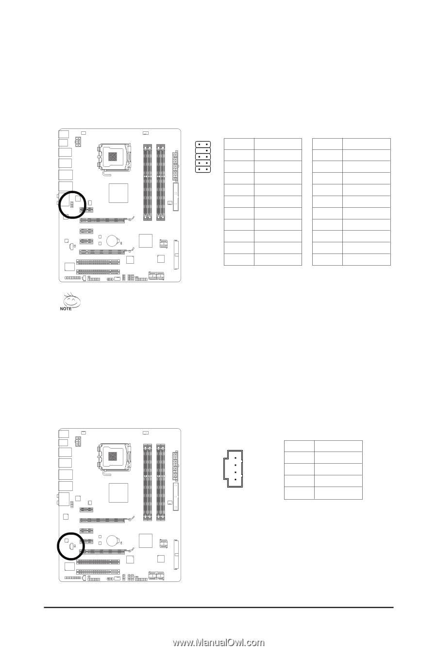
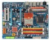
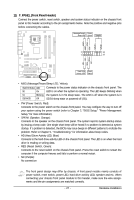
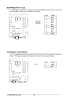
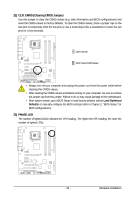
12) F_AUDIO (Front Panel Audio Header) The front panel audio header supports Intel High Definition audio (HD) and AC'97 audio. You may connect your chassis front panel audio module to this header. Make sure the wire assignments of the module connector match the pin assignments of the motherboard header. Incorrect connection between the module connector and the motherboard header will make the device unable to work or even damage it. For HD Front Panel Audio: For AC'97 Front Panel Audio: 10 9 Pin No. Definition 1 MIC2_L Pin No. 1 Definition MIC 2 1 2 3 GND MIC2_R 2 GND 3 MIC Power 4 -ACZ_DET 4 NC 5 LINE2_R 5 Line Out (R) 6 GND 6 NC 7 FAUDIO_JD 7 NC 8 No Pin 8 No Pin 9 LINE2_L 9 Line Out (L) 10 GND 10 NC • The front panel audio header supports HD audio by default. If your chassis provides an AC'97 front panel audio module, refer to the instructions on how to activate AC'97 functioninality via the audio software in Chapter 5, "Configuring 2/4/5.1/7.1-Channel Audio." • When using an AC'97 front panel audio module, you can use either the front or the back panel audio connectors, but not both at the same time. • Some chassis provide a front panel audio module that has separated connectors on each wire instead of a single plug. For information about connecting the front panel audio module that has different wire assignments, please contact the chassis manufacturer. 13) CD_IN (CD In Connector, Black) You may connect the audio cable that came with your optical drive to the header. 1 Pin No. Definition 1 CD-L 2 GND 3 GND 4 CD-R GA-X48-DS4 Motherboard - 28 -
-
 1
1 -
2
-
3
-
4
-
5
-
6
-
7
-
8
-
9
-
10
-
11
-
12
-
13
-
14
-
15
-
16
-
17
-
18
-
19
-
20
-
21
-
22
-
 23
23 -
 24
24 -
 25
25 -
 26
26 -
 27
27 -
 28
28 -
 29
29 -
 30
30 -
 31
31 -
 32
32 -
 33
33 -
34
-
35
-
36
-
37
-
38
-
39
-
40
-
41
-
42
-
43
-
44
-
45
-
46
-
47
-
48
-
49
-
50
-
51
-
52
-
53
-
54
-
55
-
56
-
57
-
58
-
59
-
60
-
61
-
62
-
63
-
64
-
65
-
66
-
67
-
68
-
69
-
70
-
71
-
72
-
73
-
74
-
75
-
76
-
77
-
78
-
79
-
80
-
81
-
82
-
83
-
84
-
85
-
86
-
87
-
88
-
89
-
90
-
91
-
92
-
93
-
94
-
95
-
96
-
97
-
98
-
99
-
100
-
101
-
102
-
103
-
104
-
105
-
106
-
107
-
108
-
109
-
110
-
111
-
112
 |
 |