Gigabyte GA-Z87X-UD7 TH User Manual - Page 30
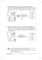
GSATA3 6/7/8/9 SATA 6Gb/s Connectors, Controlled by Marvell, 88SE9230 Chip, Z87 Chipset, ports RAID 0
 |
View all Gigabyte GA-Z87X-UD7 TH manuals
Add to My Manuals
Save this manual to your list of manuals |
Page 30 highlights
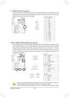
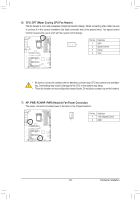
8) SATA3 0/1/2/3/4/5 (SATA 6Gb/s Connectors, Controlled by Intel® Z87 Chipset) The SATA connectors conform to SATA 6Gb/s standard and are compatible with SATA 3Gb/s and SATA 1.5Gb/s standard. Each SATA connector supports a single SATA device. The Intel® Chipset supports RAID 0, RAID 1, RAID 5, and RAID 10. Refer to Chapter 3, "Configuring SATA hard drives," for instructions on configuring a RAID array. G.QBOFM G.QBOFM G.QPBinOFNMo. Definition 1 GND SATA3 2 TXP 3 TXN 7 1 4 GND 7 1 5 RXN 531 420 6 RXP 7 GND DEBUG PORT 9) GSATA3 6/7/8/9 (SATA 6Gb/s Connectors, Controlled by Marvell® 88SE9230 Chip) The SATA connectors conform to SATA 6Gb/s standard and are compatible with SATA 3Gb/s and SATA 1.5Gb/s standard. Each SATA connector supports a single SATA device. The Marvell® 88SE9230 chip supports RAID 0, RAID 1, and RAID 10. Refer to Chapter 3, "Configuring SATA Hard Drive(s)," for instructions on configuring a RAID array. G.QBOFM G.QBOFM Pin No. Definition GSATA3 1 GND 2 TXP 7 1 97 3 TXN 7 1 86 4 GND 5 RXN 6 RXP 7 GND •• A RAID 0 or RAID 1 configuration requires at least two hard drives. If more than two hard drives EBUG are to be used, the total number of hard drives must be an even number. ORT •• A RAID 5 configuration requires at least three hard drives. (The total number of hard drives does not have to be an even number.) •• A RAID 10 configuration requires four hard drives. Hardware Installation - 30 -
-
 1
1 -
2
-
3
-
4
-
5
-
6
-
7
-
8
-
9
-
10
-
11
-
12
-
13
-
14
-
15
-
16
-
17
-
18
-
19
-
20
-
21
-
22
-
23
-
24
-
 25
25 -
 26
26 -
 27
27 -
 28
28 -
 29
29 -
 30
30 -
 31
31 -
 32
32 -
 33
33 -
 34
34 -
 35
35 -
36
-
37
-
38
-
39
-
40
-
41
-
42
-
43
-
44
-
45
-
46
-
47
-
48
-
49
-
50
-
51
-
52
-
53
-
54
-
55
-
56
-
57
-
58
-
59
-
60
-
61
-
62
-
63
-
64
-
65
-
66
-
67
-
68
-
69
-
70
-
71
-
72
-
73
-
74
-
75
-
76
-
77
-
78
-
79
-
80
-
81
-
82
-
83
-
84
-
85
-
86
-
87
-
88
-
89
-
90
-
91
-
92
-
93
-
94
-
95
-
96
-
97
-
98
-
99
-
100
-
101
-
102
-
103
-
104
-
105
-
106
-
107
-
108
-
109
-
110
-
111
-
112
-
113
-
114
-
115
-
116
-
117
-
118
-
119
-
120
-
121
-
122
-
123
-
124
-
125
-
126
-
127
-
128
 |
 |
