Hayward OnCommand® Model: ALL MODELS Installation
Hayward OnCommand® Manual
 |
View all Hayward OnCommand® manuals
Add to My Manuals
Save this manual to your list of manuals |
Hayward OnCommand® manual content summary:
- Hayward OnCommand® | Model: ALL MODELS Installation - Page 1
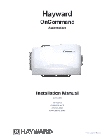
Hayward OnCommand Automation Installation Manual for models ONCOM ONCOM-ACT ONCOM-RC ONCOM-ACT-RC www.hayward.com - Hayward OnCommand® | Model: ALL MODELS Installation - Page 2
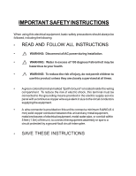
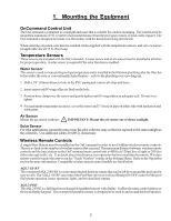
electrical equipment, basic safety precautions should always be followed, including the following: • READ AND FOLLOW ALL INSTRUCTIONS • ! WARNING: Disconnect all AC power during installation. • ! WARNING: Water in excess of 100 degrees Fahrenheit may be hazardous to your health. • ! WARNING - Hayward OnCommand® | Model: ALL MODELS Installation - Page 3
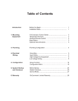
Mounting Equipment 2. Plumbing 3. Electrical Wiring 4. Configuration 5. System Startup and Checkout 6. Warranty Before You Begin 1 Installation Steps 1 OnCommand Control Center 2 Temperature Sensors 2 Wireless Remote Control 2 Base Station 3 Optional Valve Actuators 3 Plumbing Configuration - Hayward OnCommand® | Model: ALL MODELS Installation - Page 4
only) (1) Goldline AQL2-BASE-RF/AQL2-SS-RF remote control (ONCOM-RC, ONCOM-ACT-RC only) (1) 120 VAC Power input cable (G1-016067) (1) 240 VAC Power input cable (G1-016084) (1) Mounting bracket with screws (1) Installation manual (1) Operation manual What's NOT Included Some of the additional items - Hayward OnCommand® | Model: ALL MODELS Installation - Page 5
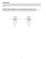
maximum distance between wireless remote controls and the base station on the OnCommand main control unit is 400 feet (120m) line of sight or 200 feet (60m) through walls, etc. If in doubt about the distance, test operation before installing the remote. Wireless remote controls require the user to - Hayward OnCommand® | Model: ALL MODELS Installation - Page 6
the base station, remove the middle knockout on the left side of the OnCommand main control unit, insert the base station, and then tighten the nut from the inside. Also refer to the Base Station installation manual and the diagram on page 13. Optional Valve Actuators (included with ONCOM-ACT - Hayward OnCommand® | Model: ALL MODELS Installation - Page 7
CLEANER PRESSURE CLEANER Some important notes regarding the OnCommand control of Standard Pool/Spa systems (refer to the Operation section for more information): In Pool/Spa Config., select: Pool/Spa Setup Pool and Spa 1. The OnCommand can be programmed to accommodate spa spillover, if desired - Hayward OnCommand® | Model: ALL MODELS Installation - Page 8
to wiring the OnCommand • Follow all local and NEC (CEC if applicable) codes • Use copper conductors only The OnCommand requires both high OnCommand control relays. High Voltage Wiring Input Power Wiring The OnCommand requires 120VAC, .6A or 240VAC, .3A input power to operate the control - Hayward OnCommand® | Model: ALL MODELS Installation - Page 9
6 - Hayward OnCommand® | Model: ALL MODELS Installation - Page 10
below AND to configure the control logic according to the Operation Instructions. Lights: A ground fault circuit breaker must be used to supply power for high voltage pool/spa lighting. Low voltage lights will require an external transformer. For lighting systems that have both a light source - Hayward OnCommand® | Model: ALL MODELS Installation - Page 11
for a generic connection. The manuals supplied with most heaters also include specific wiring instructions for connecting the heater to an external control (usually identified as "2-wire" remote control). For millivolt or line voltage heaters, contact Goldline Tech support, 908-355-7995. Refer to - Hayward OnCommand® | Model: ALL MODELS Installation - Page 12
Generic Heaters 1. Wire heater to 120/240V power source per the instructions in the heater manual. The OnCommand does NOT control the power going to the heater. 2. Wire the OnCommand dry contact heater output per the diagram below. Many internal parts of the heater can get very hot--see the heater - Hayward OnCommand® | Model: ALL MODELS Installation - Page 13
Hayward Heaters Refer to the instructions in the heater manual for "2-wire Remote Thermostat" operation under "Remote Control Connections" and the diagram below: 1. Turn off power to heater. 2. Wire OnCommand to terminals 1 & 2 (see diagram). 3. Leave jumper attached to terminals 4 & 5. 4. Move " - Hayward OnCommand® | Model: ALL MODELS Installation - Page 14
a mistake, change the mode to "POOL" or "SPA" which then disables the remote control by the OnCommand. To prevent this: Remove the heater control box. 3. Remove the jumper for the "fireman's switch. 4. Wire to the OnCommand using wire rated for 105°C minimum. Fireman's Switch Operating 'Control - Hayward OnCommand® | Model: ALL MODELS Installation - Page 15
must be set to 001 when using the VSC with the OnCommand. Refer to the TriStar Pump Owner's Manual (IS3220VSC) and Hayward document IS3220VSCAQLL for specific instructions on setting the pump address. Temperature Sensors The OnCommand utilizes 10K ohm thermistor type sensors. Three sensors (water - Hayward OnCommand® | Model: ALL MODELS Installation - Page 16
station into the "wireless" connector on the main PCB in the OnCommand control unit. Goldline Aqua Rite or Hayward Swimpure Chlorinator The OnCommand can control one or more Goldline Aqua Rite or Hayward Swimpure chlorinators when additional sanitizing capacity is required. A 4 wire connection is - Hayward OnCommand® | Model: ALL MODELS Installation - Page 17
, the button can be programmed to turn on the pool light, turn on the bug light, turn off the pool cleaner, and turn on the music all at the same time. This convenient feature can be assigned to either one of the Aux buttons, the Lights button or the Valve 3 automated function. Before assigning and - Hayward OnCommand® | Model: ALL MODELS Installation - Page 18
while "Group Control" is displayed. The setpoint will change and be retained as the new normal heater setpoint. Super Chlorinate (requires external chlorinator) If a Hayward Swimpure or Goldline Aqua Rite chlorinator is used, the OnCommand can be programmed to Super Chlorinate the pool or spa while - Hayward OnCommand® | Model: ALL MODELS Installation - Page 19
(see Settings Menu in the Operation manual). If disabled (default), all displays relating to the chlorinator will be suppressed. When the chlorinator is enabled, the OnCommand will automatically detect and control any Aqua Rite/Swimpure(s) that is installed in the system. Display Allows for the - Hayward OnCommand® | Model: ALL MODELS Installation - Page 20
, then the OnCommand will switch the pool/spa valves to the "pool only" position at the start of the programmed pool filtering time period or when the super-chlorinate function is turned on. This may be desirable on some systems with in-floor cleaners because it allows the cleaner to operate all the - Hayward OnCommand® | Model: ALL MODELS Installation - Page 21
message on display). Pushing the filter button a second time will override the heater cooldown operation and turn the filter pump off. Heater Extend If "Enabled", the filter extend logic keeps the filter pump running beyond the normal turn-off time until the pool (or spa) is heated up to the desired - Hayward OnCommand® | Model: ALL MODELS Installation - Page 22
NOT cause the filter pump to turn on, it will only delay the turn off time when solar is operating. Solar Priority If both "Solar Control" and "Heater Control" are enabled, the Solar Priority feature will keep the conventional heater off whenever solar heat is available. This provides the most cost - Hayward OnCommand® | Model: ALL MODELS Installation - Page 23
the LIGHTS button is pressed. The lights relay will turn off automatically after a programmed time (see Timers Menu in Operation Manual). The LIGHTS button can also be used to turn the output off. Low Speed of a 2-speed Filter Pump - the OnCommand will turn on the lights relay whenever the low speed - Hayward OnCommand® | Model: ALL MODELS Installation - Page 24
, this feature will override the function (Manual On/Off, Countdown Timer, Timeclock) selected above and turn the lights relay off when: filter pump is off, first 3 minutes of filter pump operation (allows the pump to prime and get water flowing), when the pool/spa suction return valves are in any - Hayward OnCommand® | Model: ALL MODELS Installation - Page 25
and then will turn off automatically after a programmed time (see Timers Menu, Operation Manual). The AUX button can also be used to turn the output off. Low Speed of a 2-speed Filter Pump - the OnCommand will operate the aux relay whenever the low speed operation of the filter pump is required. It - Hayward OnCommand® | Model: ALL MODELS Installation - Page 26
the selected freeze temperature threshold, the OnCommand will turn on the aux relay to circulate the water. IMPORTANT: this only enables operation of the AUX output during freeze--see the "Filter Pump Config." menu to enable freeze protection for the main circulation system. Aux1 Pump Speed This is - Hayward OnCommand® | Model: ALL MODELS Installation - Page 27
to previous/next configuration menu Valve3 Function Timeclock (default) - the valve turns on/off at the times set for the valve3 timeclock in the Timers Menu (see Operations Manual). Solar - the valve operates when the filter pump is running and solar heat is available and the water is less than - Hayward OnCommand® | Model: ALL MODELS Installation - Page 28
Settings, Timers, and Configuration menus from any of the OnCommand's remote display/keypads. When disabled, the remote display/keypads will only show the default menu and allow on/off control via the pushbuttons. Note that the function of the OnCommand's built-in display/keypad is unchanged by this - Hayward OnCommand® | Model: ALL MODELS Installation - Page 29
breakers are installed in the OnCommand subpanel. 2. All wiring is performed according to NEC and local codes. 3. The OnCommand is properly grounded and bonded. 4. The OnCommand is properly configured to control all desired functions. Program Automatic Operation Refer to the programming flow chart - Hayward OnCommand® | Model: ALL MODELS Installation - Page 30
. For more detailed instructions on control and operation of the OnCommand system, refer to the Operation Manual. Service Mode Service mode disables all automatic control operation and is intended to be used when servicing the pool system. To enter service mode, push the SERVICE button once on the - Hayward OnCommand® | Model: ALL MODELS Installation - Page 31
www.hayward.com. WARRANTY EXCLUSIONS: 1. Material supplied or workmanship performed by others in process of installation. 2. Damage resulting from improper installation including installation on pools larger than the product rating. 3. Problems resulting from failure to install, operate or maintain - Hayward OnCommand® | Model: ALL MODELS Installation - Page 32
is running (not scheduled) countdown time remaining heater control status system manual off check system error filter speed spa heater temperature pool heater temperature spa solar temperature pool solar temperature superchlorinate spa chlorinator setting pool chlorinator setting spa high/low speed
-
 1
1 -
 2
2 -
 3
3 -
 4
4 -
 5
5 -
 6
6 -
 7
7 -
8
-
9
-
10
-
11
-
12
-
13
-
14
-
15
-
16
-
17
-
18
-
19
-
20
-
21
-
22
-
23
-
24
-
25
-
26
-
27
-
28
-
29
-
30
-
31
-
32
 |
 |
Hayward
OnCommand
Automation
Installation Manual
ONCOM
ONCOM-ACT
ONCOM-RC
ONCOM-ACT-RC
www.hayward.com
for models