Hayward OnCommand® Model: ALL MODELS Installation - Page 8
Electrical Wiring
 |
View all Hayward OnCommand® manuals
Add to My Manuals
Save this manual to your list of manuals |
Page 8 highlights
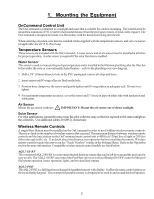
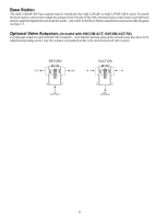
3. Electrical Wiring • Ensure that Power is disconnected prior to wiring the OnCommand • Follow all local and NEC (CEC if applicable) codes • Use copper conductors only The OnCommand requires both high and low voltage connections. To gain access to the wiring compartments, open the door and remove the left and right panel covers. A divider separates the OnCommand into low voltage and high voltage compartments. All low voltage connections will be made to the printed circuit board (PCB) on the left side of the divider. These connections include actuators, sensors, heaters, etc. All high voltage connections such as PCB input power, pumps, lights, etc. are made on the right side of the divider. Grounding A ground bus bar is located in the high voltage compartment of the OnCommand. Connect a ground wire from the primary electrical panel to this ground bus bar. Also use this ground bar to ground each piece of high voltage (120 or 240VAC) equipment that is connected to the OnCommand control relays. High Voltage Wiring Input Power Wiring The OnCommand requires 120VAC, .6A or 240VAC, .3A input power to operate the control logic circuits under maximum load. This power should come from a circuit breaker rated at 125% of the intended load or the next higher size available. Leads are supplied for input wiring as shown above. The green ground wire must be connected to the ground bus bar before connecting to input power. The OnCommand can be powered by either 120VAC or 240VAC depending on which voltage is available at the mounting location. Two cables are provided. Select the proper cable for your desired input power and plug the connector into the J1 socket shown on the diagram above. Route the cable leads under the center divider cover and refer to the diagram on the following page for proper connections to the input leads. 5
-
 1
1 -
2
-
 3
3 -
 4
4 -
 5
5 -
 6
6 -
 7
7 -
 8
8 -
 9
9 -
 10
10 -
 11
11 -
 12
12 -
 13
13 -
14
-
15
-
16
-
17
-
18
-
19
-
20
-
21
-
22
-
23
-
24
-
25
-
26
-
27
-
28
-
29
-
30
-
31
-
32
 |
 |
