HP 8/20q HP StorageWorks 8Gb Simple SAN Connection Kit quick start instruction - Page 2
Hardware installation instructions - fc 8 ports active switch
 |
View all HP 8/20q manuals
Add to My Manuals
Save this manual to your list of manuals |
Page 2 highlights
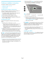
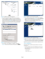
Hardware installation instructions The hardware installation has three components: • Installing the storage components • Installing the switch • Installing the HBAs Installing the storage components Install your HP storage components (purchased separately; not included in the 8Gb Simple SAN Connection Kit). 1. If not already installed, install the MSA or EVA storage array using the documentation supplied with the unit. 2. Connect the power cables to the power source. 3. Power on the storage array and allow it to initialize. 4. For EVA storage, install the HP StorageWorks Command View EVA v7.0 or higher software. Installing the switch Install the HP StorageWorks 8/20q Fibre Channel Switch as follows: 1. Mount the switch on a flat surface or in a rack: • Place the switch on a flat surface and stack. Attach the four adhesive rubber feet to the bottom of the switch. Or, • Mount the switch in a 19" EIA rack following the steps in the HP StorageWorks 8/20q Switch Rack-Mount Kit quick start installation instructions. 2. Install each SFP transceiver by inserting the transceiver into any of the active switch ports and pressing gently until it snaps in place. The transceiver will fit only one way. If the transceiver does not install under gentle pressure, flip it over and try again. NOTE: An HP Small Form-factor Pluggable (SFP) transceiver is required for each switch port that will be connected to a device or another switch. Only HP SFPs are supported for use in the switch. On a new HP StorageWorks 8/20q Fibre Channel Switch, ports 0-7 are active. The switch supports 2 Gb, 4 Gb, and 8 Gb transmission with HP 8 Gb fiber optic transceivers. 3. Apply power to the switch by attaching the AC power cord to the receptacle on the back of the switch and to the power source. The switch runs its self tests and begins normal operation-this may take a few minutes. 4. Check the switch LEDs (Figure 1) to verify that the Input Power LED is illuminated, the Heartbeat LED is blinking (once per second), and the System Fault LED is not illuminated. 1 2 3 Figure 1 Switch LEDs 1 Input Power LED 2 Heartbeat LED 3 System Fault LED 5. Connect the switch Ethernet port to the: • LAN that is used to connect the management station that will run HP StorageWorks Simple SAN Connection Manager (see Software installation instructions, page 3). • Other servers in the SAN. IMPORTANT: Do not configure the switch at this time. The HP StorageWorks Simple SAN Connection Manager software will prompt you to set the switch IP address, administrator password, and default zoning when you first start that software. 6. Connect the FC cables between the installed transceivers and their corresponding devices and switches. Each port auto-negotiates the proper port type with the connected device or switch. Installing the HBAs Install an HBA on each server (Figure 2). For additional information, see the instructions in the HP StorageWorks 81Q PCI-e FC HBA quick start installation instructions. Page 2
-
 1
1 -
 2
2 -
 3
3 -
 4
4 -
 5
5 -
 6
6 -
 7
7
 |
 |
