HP A9890A Smart Array 6400 Series Controllers User Guide - Page 51
Diagnosing array problems, Controller board runtime LEDs
 |
UPC - 829160079530
View all HP A9890A manuals
Add to My Manuals
Save this manual to your list of manuals |
Page 51 highlights
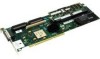
51 Diagnosing array problems In this section Controller board runtime LEDs ...51 Cache module LEDs...53 Diagnostic tools ...54 Controller board runtime LEDs LED ID 0 1 Color Amber Amber 2 Blue 3 Green NOTE: During server power-up, each runtime LED illuminates randomly until POST has finished. LED name and interpretation CR100: Diagnostics Error LED. CR101: Drive Failure LED. A physical drive connected to the controller has failed. CR102: SCSI Bus Active LED. At least one of the SCSI buses on the controller is active. CR103: XOR Active LED. The controller is calculating parity data.
-
 1
1 -
2
-
3
-
4
-
5
-
6
-
7
-
8
-
9
-
10
-
11
-
12
-
13
-
14
-
15
-
16
-
17
-
18
-
19
-
20
-
21
-
22
-
23
-
24
-
25
-
26
-
27
-
28
-
29
-
30
-
31
-
32
-
33
-
34
-
35
-
36
-
37
-
38
-
39
-
40
-
41
-
42
-
43
-
44
-
45
-
 46
46 -
 47
47 -
 48
48 -
 49
49 -
 50
50 -
 51
51 -
 52
52 -
 53
53 -
 54
54 -
 55
55 -
 56
56 -
57
-
58
-
59
-
60
-
61
-
62
-
63
-
64
-
65
-
66
-
67
-
68
 |
 |

51
Diagnosing array problems
In this section
Controller board runtime LEDs
....................................................................................................
51
Cache module LEDs
.....................................................................................................................
53
Diagnostic tools
............................................................................................................................
54
Controller board runtime LEDs
NOTE:
During server power-up, each runtime LED illuminates
randomly until POST has finished.
LED ID
Color
LED name and interpretation
0
Amber
CR100: Diagnostics Error LED.
1
Amber
CR101: Drive Failure LED. A physical drive connected to the controller
has failed.
2
Blue
CR102: SCSI Bus Active LED. At least one of the SCSI buses on the
controller is active.
3
Green
CR103: XOR Active LED. The controller is calculating parity data.