HP A9890A Smart Array 6400 Series Controllers User Guide - Page 52
LED ID, Color, LED name and interpretation, Controller CPU activity level, Item 6 status
 |
UPC - 829160079530
View all HP A9890A manuals
Add to My Manuals
Save this manual to your list of manuals |
Page 52 highlights
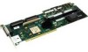
52 HP Smart Array 6400 Series Controllers User Guide LED ID 4 Color Green 5 Blue 6 Green 7 Green 8 Amber 9 Green LED name and interpretation CR104: Command Outstanding LED. The controller is working on a command. CR105: Heartbeat LED. This LED flashes every 2 seconds, unless the controller is malfunctioning. CR106: Gas Pedal LED. This LED, together with item 7, indicates the amount of controller CPU activity. For details, refer to the following table. CR107: Idle Task LED. This LED, together with item 6, indicates the amount of controller CPU activity. For details, refer to the following table. CR11: Battery Status LED. For interpretation, refer to Cache module LEDs (on page 53). CR10: Battery Charging LED. For interpretation, refer to Cache module LEDs (on page 53). Controller CPU activity level 0-25% 25-50% 50-75% 75-100% Item 6 status Off Blinking On steadily On steadily Item 7 status Blinking Off Off On steadily
-
 1
1 -
2
-
3
-
4
-
5
-
6
-
7
-
8
-
9
-
10
-
11
-
12
-
13
-
14
-
15
-
16
-
17
-
18
-
19
-
20
-
21
-
22
-
23
-
24
-
25
-
26
-
27
-
28
-
29
-
30
-
31
-
32
-
33
-
34
-
35
-
36
-
37
-
38
-
39
-
40
-
41
-
42
-
43
-
44
-
45
-
46
-
 47
47 -
 48
48 -
 49
49 -
 50
50 -
 51
51 -
 52
52 -
 53
53 -
 54
54 -
 55
55 -
 56
56 -
 57
57 -
58
-
59
-
60
-
61
-
62
-
63
-
64
-
65
-
66
-
67
-
68
 |
 |
