HP C3180A Service Manual - Page 118
Ć54, Removal and Replacement
 |
View all HP C3180A manuals
Add to My Manuals
Save this manual to your list of manuals |
Page 118 highlights
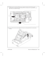
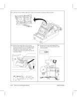
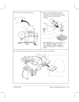
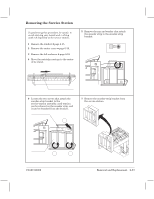
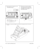
25 Set the carriage assembly upsideĆdown on a flat surface. 26 Using a small, standard screwdriver, remove the left and right belt clamps from the carriage assembly. Belt clamp CAUTION Be careful not to damage the clamps. Reassembling: Correctly install the clamps, so that they don't fall out during plotter operation! 27 Remove the main drive belt from the carriage assembly. Main drive belt Calibration: After having reassembled the plotter, perform the cartridgeĆalignment routine D chapter 7. 6Ć54 Removal and Replacement C3187Ć90000
-
 1
1 -
2
-
3
-
4
-
5
-
6
-
7
-
8
-
9
-
10
-
11
-
12
-
13
-
14
-
15
-
16
-
17
-
18
-
19
-
20
-
21
-
22
-
23
-
24
-
25
-
26
-
27
-
28
-
29
-
30
-
31
-
32
-
33
-
34
-
35
-
36
-
37
-
38
-
39
-
40
-
41
-
42
-
43
-
44
-
45
-
46
-
47
-
48
-
49
-
50
-
51
-
52
-
53
-
54
-
55
-
56
-
57
-
58
-
59
-
60
-
61
-
62
-
63
-
64
-
65
-
66
-
67
-
68
-
69
-
70
-
71
-
72
-
73
-
74
-
75
-
76
-
77
-
78
-
79
-
80
-
81
-
82
-
83
-
84
-
85
-
86
-
87
-
88
-
89
-
90
-
91
-
92
-
93
-
94
-
95
-
96
-
97
-
98
-
99
-
100
-
101
-
102
-
103
-
104
-
105
-
106
-
107
-
108
-
109
-
110
-
111
-
112
-
 113
113 -
 114
114 -
 115
115 -
 116
116 -
 117
117 -
 118
118 -
 119
119 -
 120
120 -
 121
121 -
 122
122 -
 123
123 -
124
-
125
-
126
-
127
-
128
-
129
-
130
-
131
-
132
-
133
-
134
-
135
-
136
-
137
-
138
-
139
-
140
-
141
-
142
-
143
-
144
-
145
-
146
-
147
-
148
-
149
-
150
-
151
-
152
-
153
-
154
-
155
-
156
-
157
-
158
-
159
-
160
-
161
-
162
-
163
-
164
-
165
-
166
-
167
-
168
-
169
-
170
-
171
-
172
-
173
-
174
-
175
-
176
-
177
-
178
-
179
-
180
-
181
-
182
-
183
-
184
-
185
-
186
-
187
-
188
-
189
-
190
-
191
-
192
-
193
-
194
-
195
-
196
-
197
-
198
-
199
-
200
-
201
-
202
-
203
-
204
-
205
-
206
-
207
-
208
-
209
-
210
-
211
-
212
-
213
-
214
-
215
-
216
-
217
-
218
-
219
-
220
-
221
-
222
-
223
-
224
-
225
-
226
-
227
-
228
-
229
-
230
-
231
-
232
-
233
-
234
-
235
-
236
-
237
-
238
-
239
-
240
-
241
-
242
-
243
-
244
-
245
-
246
 |
 |
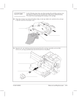
25
Set the carriage assembly upsideĆdown on a flat surface.
26
Using a small, standard screwdriver, remove the left and right belt clamps from the
carriage assembly.
Belt clamp
27
Remove the main drive belt from the carriage assembly.
Main drive belt
CAUTION
Be careful not to damage the clamps.
Calibration:
After having reassembled the plotter, perform the cartridgeĆalignment
routine
D
chapter 7.
Reassembling
: Correctly install the
clamps, so that they don't fall out during
plotter operation!
6Ć54
Removal and Replacement
C3187Ć90000