HP Cisco MDS 9120 Cisco MDS 9500 Series Hardware Installation Guide (OL-17467- - Page 113
Providing Power to a DC Power Supply in the Cisco MDS 9509 Director,
 |
View all HP Cisco MDS 9120 manuals
Add to My Manuals
Save this manual to your list of manuals |
Page 113 highlights
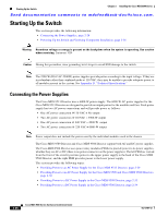
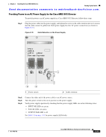
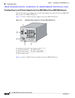
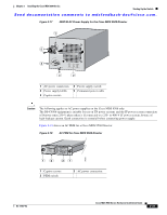
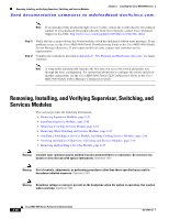
Chapter 2 Installing the Cisco MDS 9500 Series Starting Up the Switch Send documentation comments to [email protected]. Providing Power to a DC Power Supply in the Cisco MDS 9509 Director Warning Before performing any of the following procedures, ensure that power is removed from the DC circuit. Statement 1003 Warning When installing or replacing the unit, the ground connection must always be made first and disconnected last. Statement 1046 For more information on DC power supply for the MDS 9509 Director, see the "System Grounding" section on page 2-17. Figure 2-20 shows the 2500-W DC power supply. Figure 2-20 2500-W DC Power Supply for the Cisco MDS 9509 Director 1 99360 5 I 0 4 INPUT FAN OUTPUT OK OK FAIL 3 2 1 Terminal block cover 2 Power supply LEDs 3 Captive screw 4 Power supply switch 5 Terminal block Note Use 90-degree C fine-stranded copper conductors for North American installations. To provide power to a DC power supply in a Cisco MDS 9509 Director, follow these steps: Step 1 Ensure that all power is off. Locate the circuit breaker on the panel board that services the DC circuit. Switch the circuit breaker to the off position, and then tape the switch handle of the circuit breaker in the off position. OL-17467-02 Cisco MDS 9500 Series Hardware Installation Guide 2-33
-
 1
1 -
2
-
3
-
4
-
5
-
6
-
7
-
8
-
9
-
10
-
11
-
12
-
13
-
14
-
15
-
16
-
17
-
18
-
19
-
20
-
21
-
22
-
23
-
24
-
25
-
26
-
27
-
28
-
29
-
30
-
31
-
32
-
33
-
34
-
35
-
36
-
37
-
38
-
39
-
40
-
41
-
42
-
43
-
44
-
45
-
46
-
47
-
48
-
49
-
50
-
51
-
52
-
53
-
54
-
55
-
56
-
57
-
58
-
59
-
60
-
61
-
62
-
63
-
64
-
65
-
66
-
67
-
68
-
69
-
70
-
71
-
72
-
73
-
74
-
75
-
76
-
77
-
78
-
79
-
80
-
81
-
82
-
83
-
84
-
85
-
86
-
87
-
88
-
89
-
90
-
91
-
92
-
93
-
94
-
95
-
96
-
97
-
98
-
99
-
100
-
101
-
102
-
103
-
104
-
105
-
106
-
107
-
 108
108 -
 109
109 -
 110
110 -
 111
111 -
 112
112 -
 113
113 -
 114
114 -
 115
115 -
 116
116 -
 117
117 -
 118
118 -
119
-
120
-
121
-
122
-
123
-
124
-
125
-
126
-
127
-
128
-
129
-
130
-
131
-
132
-
133
-
134
-
135
-
136
-
137
-
138
-
139
-
140
-
141
-
142
-
143
-
144
-
145
-
146
-
147
-
148
-
149
-
150
-
151
-
152
-
153
-
154
-
155
-
156
-
157
-
158
-
159
-
160
-
161
-
162
-
163
-
164
-
165
-
166
-
167
-
168
-
169
-
170
-
171
-
172
-
173
-
174
-
175
-
176
-
177
-
178
-
179
-
180
-
181
-
182
-
183
-
184
-
185
-
186
-
187
-
188
-
189
-
190
-
191
-
192
-
193
-
194
-
195
-
196
-
197
-
198
-
199
-
200
-
201
-
202
-
203
-
204
-
205
-
206
-
207
-
208
-
209
-
210
-
211
-
212
-
213
-
214
-
215
-
216
-
217
-
218
-
219
-
220
-
221
-
222
-
223
-
224
-
225
-
226
-
227
-
228
-
229
-
230
-
231
-
232
-
233
-
234
-
235
-
236
-
237
-
238
-
239
-
240
-
241
-
242
-
243
-
244
-
245
-
246
-
247
-
248
-
249
-
250
-
251
-
252
-
253
-
254
-
255
-
256
-
257
-
258
-
259
-
260
-
261
-
262
-
263
-
264
-
265
-
266
-
267
-
268
-
269
-
270
-
271
-
272
-
273
-
274
-
275
-
276
-
277
-
278
-
279
-
280
-
281
-
282
-
283
-
284
-
285
-
286
-
287
-
288
 |
 |
