HP Cisco MDS 9124 Cisco MDS 9100 Series Hardware Installation Guide (OL-17951- - Page 42
Installing Front Rack-Mount Brackets for Cabinets with Less Than 26 Inches of Rail Spacings
 |
View all HP Cisco MDS 9124 manuals
Add to My Manuals
Save this manual to your list of manuals |
Page 42 highlights
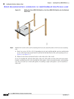
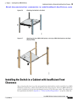
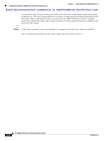
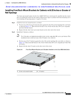
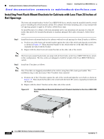
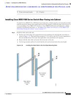
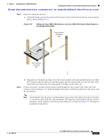
Installing the Switch in a Cabinet with Insufficient Front Clearance Chapter 2 Installing the Cisco MDS 9100 Series Send documentation comments to [email protected] Installing Front Rack-Mount Brackets for Cabinets with Less Than 26 Inches of Rail Spacings The front rack-mount brackets for the Cisco MDS 9100 Series switches must be installed onto the switch prior to installing the switch into the cabinet. For cabinets with front-mounting rails, to rear-mount with rail spacings greater or equal to 26 inches, follow these steps: To install brackets for cabinets with front-mounting rail to rear-mounting rail spacings less than 26 inches that need to be mounted backwards to maintain adequate fiber-optic clearances, follow these steps: Step 1 Install the front-rack mount brackets for cabinets with rail-to-rail spacings less than 26 inches as follows: a. Position one of the front rack-mount brackets against the side of the switch and align the screw holes as shown in Figure 2-9. Then attach the bracket to the switch with two of the three M4 screws originally provided with the bracket. b. Repeat with the other front rack-mount bracket on the other side of the switch. Note The front rack-mount bracket does not align with all three holes in the Cisco MDS 9100 Series switch in this configuration. The two screws are adequate to hold the weight of the Cisco MDS 9100 Series switch. Step 2 Install the C brackets as follows: Note Two C brackets are shipped preinstalled on the switch, using three M3 screws per bracket. This installation step is only necessary if the C brackets were removed. a. Position one of the C brackets against the side of the switch and align the screw holes as shown in Figure 2-9. Then attach the bracket to the switch with the three M3 screws originally provided with the bracket. b. Repeat with the other C bracket on the other side of the switch. Figure 2-9 Front Rack-Mount Brackets (Rotated) and C Brackets Installed on the Cisco MDS 9100 Series 2 1 2-14 Cisco MDS 9100 Series Hardware Installation Guide 113431 OL-17951-02
-
 1
1 -
2
-
3
-
4
-
5
-
6
-
7
-
8
-
9
-
10
-
11
-
12
-
13
-
14
-
15
-
16
-
17
-
18
-
19
-
20
-
21
-
22
-
23
-
24
-
25
-
26
-
27
-
28
-
29
-
30
-
31
-
32
-
33
-
34
-
35
-
36
-
 37
37 -
 38
38 -
 39
39 -
 40
40 -
 41
41 -
 42
42 -
 43
43 -
 44
44 -
 45
45 -
 46
46 -
 47
47 -
48
-
49
-
50
-
51
-
52
-
53
-
54
-
55
-
56
-
57
-
58
-
59
-
60
-
61
-
62
-
63
-
64
-
65
-
66
-
67
-
68
-
69
-
70
-
71
-
72
-
73
-
74
-
75
-
76
-
77
-
78
-
79
-
80
-
81
-
82
-
83
-
84
-
85
-
86
-
87
-
88
-
89
-
90
-
91
-
92
-
93
-
94
-
95
-
96
-
97
-
98
-
99
-
100
-
101
-
102
-
103
-
104
-
105
-
106
-
107
-
108
 |
 |