HP Cisco MDS 9140 Cisco MDS 9500 Series Hardware Installation Guide (OL-17467- - Page 154
Removing a Front Fan Module on the Cisco MDS 9506 Director, Installing a Front Fan Module on
 |
View all HP Cisco MDS 9140 manuals
Add to My Manuals
Save this manual to your list of manuals |
Page 154 highlights
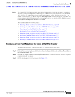
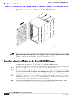
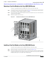
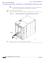
Removing and Installing Fan Modules Chapter 2 Installing the Cisco MDS 9500 Series Send documentation comments to [email protected]. Step 3 Step 4 Step 5 Tighten the captive screws to 8 in-lb. If the switch is powered on, listen for the fans; you should immediately hear them operating. If you do not hear them, ensure that the fan module is inserted completely in the chassis and the outside surface of the fan module is flush with the outside surface of the chassis. Verify that the Fan Status LED is green. If the LED is not green, one or more fans are faulty. If this occurs, contact your customer service representative for a replacement part. Note If you purchased this product through a Cisco reseller, contact the reseller directly for technical support. If you purchased this product directly from Cisco Systems, contact Cisco Technical Support at this URL: http://www.cisco.com/warp/public/687/Directory/DirTAC.shtml. Removing a Front Fan Module on the Cisco MDS 9506 Director To remove a fan module from the Cisco MDS 9506 Director, follow these steps: Step 1 Step 2 Step 3 Loosen the two captive screws on the fan module (see Figure 2-39) by turning them counterclockwise; use a flat-blade or number 2 Phillips screwdriver, if required. Grasp the fan module with both hands and pull it outward; rock it gently, if necessary, to unseat the power connector from the backplane. Pull the fan module clear of the chassis. Installing a Front Fan Module on the Cisco MDS 9506 Director To install a front fan module on the Cisco MDS 9506 Director, follow these steps: Step 1 Hold the fan module so that the Fan Status LED is at the top. Step 2 Step 3 Step 4 Step 5 Place the fan module into the front chassis cavity so it rests on the chassis, lift the fan module up slightly to align the top and bottom chassis guides, then push the fan module into the chassis until it seats in the backplane and the captive screws make contact with the chassis. Tighten the captive screws to 8 in-lb. If the switch is powered on, listen for the fans; you should immediately hear them operating. If you do not hear them, ensure that the fan module is inserted completely in the chassis and the outside surface of the fan module is flush with the outside surface of the chassis. Verify that the Fan Status LED is green. If the LED is not green, one or more fans are faulty. If this occurs, contact your customer service representative for a replacement part. 2-74 Cisco MDS 9500 Series Hardware Installation Guide OL-17467-02
-
 1
1 -
2
-
3
-
4
-
5
-
6
-
7
-
8
-
9
-
10
-
11
-
12
-
13
-
14
-
15
-
16
-
17
-
18
-
19
-
20
-
21
-
22
-
23
-
24
-
25
-
26
-
27
-
28
-
29
-
30
-
31
-
32
-
33
-
34
-
35
-
36
-
37
-
38
-
39
-
40
-
41
-
42
-
43
-
44
-
45
-
46
-
47
-
48
-
49
-
50
-
51
-
52
-
53
-
54
-
55
-
56
-
57
-
58
-
59
-
60
-
61
-
62
-
63
-
64
-
65
-
66
-
67
-
68
-
69
-
70
-
71
-
72
-
73
-
74
-
75
-
76
-
77
-
78
-
79
-
80
-
81
-
82
-
83
-
84
-
85
-
86
-
87
-
88
-
89
-
90
-
91
-
92
-
93
-
94
-
95
-
96
-
97
-
98
-
99
-
100
-
101
-
102
-
103
-
104
-
105
-
106
-
107
-
108
-
109
-
110
-
111
-
112
-
113
-
114
-
115
-
116
-
117
-
118
-
119
-
120
-
121
-
122
-
123
-
124
-
125
-
126
-
127
-
128
-
129
-
130
-
131
-
132
-
133
-
134
-
135
-
136
-
137
-
138
-
139
-
140
-
141
-
142
-
143
-
144
-
145
-
146
-
147
-
148
-
 149
149 -
 150
150 -
 151
151 -
 152
152 -
 153
153 -
 154
154 -
 155
155 -
 156
156 -
 157
157 -
 158
158 -
 159
159 -
160
-
161
-
162
-
163
-
164
-
165
-
166
-
167
-
168
-
169
-
170
-
171
-
172
-
173
-
174
-
175
-
176
-
177
-
178
-
179
-
180
-
181
-
182
-
183
-
184
-
185
-
186
-
187
-
188
-
189
-
190
-
191
-
192
-
193
-
194
-
195
-
196
-
197
-
198
-
199
-
200
-
201
-
202
-
203
-
204
-
205
-
206
-
207
-
208
-
209
-
210
-
211
-
212
-
213
-
214
-
215
-
216
-
217
-
218
-
219
-
220
-
221
-
222
-
223
-
224
-
225
-
226
-
227
-
228
-
229
-
230
-
231
-
232
-
233
-
234
-
235
-
236
-
237
-
238
-
239
-
240
-
241
-
242
-
243
-
244
-
245
-
246
-
247
-
248
-
249
-
250
-
251
-
252
-
253
-
254
-
255
-
256
-
257
-
258
-
259
-
260
-
261
-
262
-
263
-
264
-
265
-
266
-
267
-
268
-
269
-
270
-
271
-
272
-
273
-
274
-
275
-
276
-
277
-
278
-
279
-
280
-
281
-
282
-
283
-
284
-
285
-
286
-
287
-
288
 |
 |
