HP DL360 Fully-Buffered DIMM technology in HP ProLiant servers - Page 2
Abstract, Introduction, Performance barriers for traditional DIMM - proliant memory
 |
UPC - 613326948835
View all HP DL360 manuals
Add to My Manuals
Save this manual to your list of manuals |
Page 2 highlights
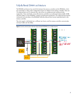
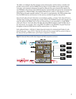
Abstract This paper describes the features, benefits, and challenges of Fully-Buffered dual inline memory module (FB-DIMM) technology. It also provides rules for populating FB-DIMM slots to achieve maximum performance in HP ProLiant servers. Introduction HP ProLiant servers provide balanced system architectures that deliver peak performance per watt of power. A balanced system architecture is one in which the three main server subsystems-processing, memory, and I/O-interact efficiently to maximize CPU performance. The introduction of dual-core processor technology challenged HP engineers to improve the performance of the memory and I/O subsystems to maintain system balance. Engineers overcame the performance bottleneck of the parallel I/O bus by migrating to a high-speed serial interface with technologies such as SerialAttached SCSI, Serial ATA, and PCI Express. Likewise, some memory subsystems are migrating to high-speed serial FB-DIMM technology to deliver scalable bandwidth and memory capacity that is not possible with traditional DIMM technologies. The paper describes the barriers that limit memory capacity and performance of servers that use traditional DIMM technologies. This paper also describes the operation of FB-DIMMs and summarizes the benefits and challenges of using FB-DIMM technology. Performance barriers for traditional DIMM Traditional DIMM architectures use a stub-bus topology with parallel branches (stubs) that connect to a shared memory bus (Figure 1). The memory bus consists of the command/address (C/A) bus and the data bus. The C/A bus consists of 21 data traces that transport command and address signals to the DIMMs. The data bus consists of 72 traces, each carrying one bit at a time (a total of 64 data bits and 8 ECC1 bits). Each DIMM connects to the data bus using a set of pin connectors2. In order for the electrical signals from the memory controller to reach the DIMM bus-pin connections at the same time, all the traces have to be the same length. This often results in circuitous traces on the motherboard between the memory controller and memory slots. Both the latency (delay) resulting from complex routing of traces and signal degradation at the bus-pin connections cause the error rate to increase as the bus speed increases. Figure 1. Stub-bus topology. An impedance discontinuity is created at each stub-bus connection. 1 Error correcting code 2 Typical SDRAM DIMMs have a total of 168 pins, DDR DIMMs have 184 pins, and DDR2 DIMMs have 240 pins. 2
-
 1
1 -
 2
2 -
 3
3 -
 4
4 -
 5
5 -
 6
6 -
 7
7 -
 8
8 -
9
-
10
 |
 |