HP DL360 Fully-Buffered DIMM technology in HP ProLiant servers - Page 5
the inbound link. For example, when using DDR2 533 DRAM on the FB-DIMM, the peak theoretical
 |
UPC - 613326948835
View all HP DL360 manuals
Add to My Manuals
Save this manual to your list of manuals |
Page 5 highlights
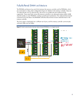
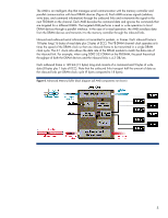
The AMB is an intelligent chip that manages serial communication with the memory controller and parallel communication with local DRAM devices (Figure 4). Each AMB receives signals (address, write data, and command information) through the outbound links and re-transmits the signal to the next FB-DIMM on the channel. Each AMB decodes the command data and ignores the commands that are targeted for a different DIMM. The targeted AMB performs a read or write operation to local DRAM devices through a parallel interface. In the case of a read operation, the AMB serializes data from the DRAM devices and transmits it to the memory controller through the inbound links. Inbound and outbound serial information is transmitted in packets, or frames. Each inbound frame is 18 bytes long (16 bytes of read data plus 2 bytes of ECC). The FB-DIMM channel clock operates at 6 times the speed of the DRAM clock so that one inbound frame to be transmitted in a single DRAM clock cycle. The 6:1 clock ratio allows the data rate of the DRAM module to match the data rate of the inbound link. For example, when using DDR2 533 DRAM on the FB-DIMM, the peak theoretical throughput of both the DRAM devices and the inbound links is 4.3 GB/sec. Each outbound frame is 120 bits (15 bytes) long and consists of a command and 9 bytes of write data (8 bytes plus 1 byte of ECC). Note that the outbound links transport half the amount of data as the inbound links per DRAM clock cycle (9 bytes compared to 18 bytes). Figure 4. Advanced Memory Buffer block diagram (all AMB components not shown) 5
-
 1
1 -
 2
2 -
 3
3 -
 4
4 -
 5
5 -
 6
6 -
 7
7 -
 8
8 -
 9
9 -
 10
10
 |
 |