HP DL360 Fully-Buffered DIMM technology in HP ProLiant servers - Page 6
Benefits, Simplified board design, Higher memory capacity
 |
UPC - 613326948835
View all HP DL360 manuals
Add to My Manuals
Save this manual to your list of manuals |
Page 6 highlights
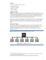
Benefits The benefits of FB-DIMM architecture include • Simplified board design • Higher memory capacity • Higher performance • Improved reliability Simplified board design FB-DIMMs use a 240-pin socket similar to that used for traditional DDR2 registered DIMMs; however, FB-DIMMs require significantly fewer signal traces. FB-DIMMs have 69 signal traces compared to 138 traces for DDR2 registered DIMMs. These traces have to be routed to every DDR2 DIMM on the channel, which complicates board design. FB-DIMMs have additional traces for the secondary links between sockets, but these traces do not add to overall routing complexity. In addition, the memory controller and AMB can compensate for signal traces of unequal length, thus eliminating the need for odd routing paths to make sure the timing is correct. The lower number of signal traces and the ability to use traces of unequal length greatly simplify board design for FBDIMMs. Higher memory capacity The point-to-point FB-DIMM architecture enables the electrical load (and signal integrity) for each channel to remain constant, even as FB-DIMMs are added. This allows system designers to have up to 8 DIMMs per channel (no rank limits) while maintaining a low soft error rate (Figure 5). In comparison, PC2-3200 SDRAM can have a maximum of 2 dual-rank DIMMs (or 4 single-rank DIMMs) per channel4. Figure 5. The FB-DIMM architecture allows up to 8 FB-DIMM sockets per channel. 4 For information about single-rank and dual-rank DIMMs, refer to Memory technology evolution: an overview of system memory technologies technology brief at http://h18004.www1.hp.com/products/servers/technology/whitepapers/adv-technology.html. 6
-
 1
1 -
 2
2 -
 3
3 -
 4
4 -
 5
5 -
 6
6 -
 7
7 -
 8
8 -
 9
9 -
 10
10
 |
 |
